SYSTEM FEATURES Product Summary
Feature of EXCESS-HYBRIDⅡ
Know the features of EXCESS-HYBRIDⅡ
About EXCESS-HYBRIDⅡ
The EXCESS-HYBRID II is a CAD/CAM system for die design and manufacturing that incorporates our unique hybrid technology based on the concept of 'More accurate in 3D design, faster in 2D design'. 2D and 3D data can be handled simultaneously in the same system, making it an effective CAD/CAM system for die design and manufacturing that involves trial and error.
Advanced 3D functions provide powerful support for upstream die design, such as the layout design of progressive press dies and the cavity core design of plastic dies. In addition, commercially available standard part data are incorporated in the die structure design, which allows the efficiency of die design work to be improved by following the conventional design method while enhancing the functions of conventional two-dimensional designs.
As a CAD/CAM-integrated system, machining attributes are added to the CAD data, enabling the CAM side to create machining data with a simple operation, and a rich variety of machining patterns support the machining site.
A "true" hybrid system that transcends 2D/3D boundaries enables shorter lead times for mold design and manufacturing.
Unique Hybrid Technologies
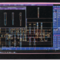
Drawing concepts not found in conventional CAD are incorporated. Adding 3D information to each 2D part drawing enables 3D from the drawing, 2D designing while displaying 3D model in the drawing, and insertion of 3D model in the drawing etc. We provide hybrid design environment with unique technology combining drawing and modeling, which makes it easy for the operator to visually confirm and judge, and allows intuitive operation without interruption of thought.
Drawing View
Model View
Multifunctional drawing and drafting commands
The EXCESS series started more than 30 years ago with 2D CAD exclusively for mold design. As you continue to develop the functionality, you will find a wealth of features to help you create drawings efficiently, including basic drawing commands as well as many useful sectioning and clearance and relief creation commands. Even after the evolution to EXCESS-HYBRID II, we have continued to add and enhance functions. For example, by adding geometric constraints that are useful in the geometry modification function, it has become possible to perform shape modifications in tandem.
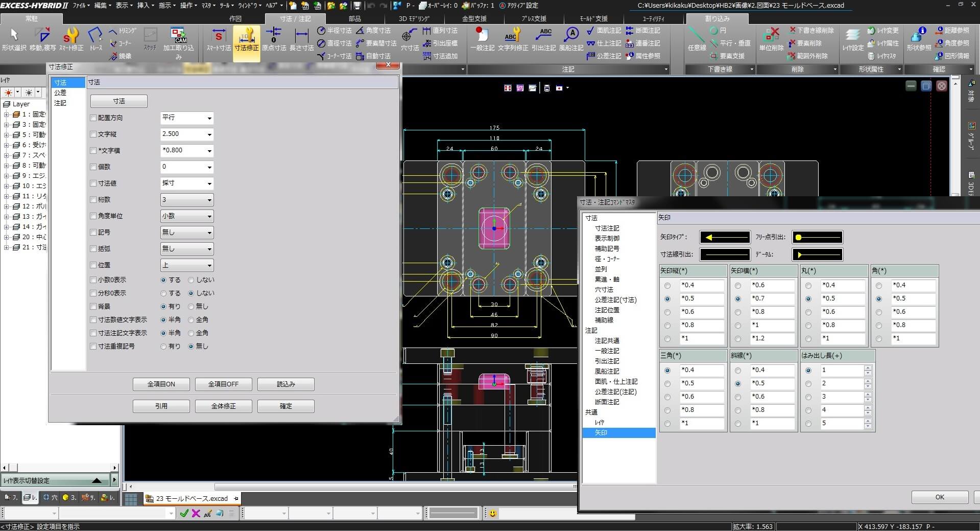
Die manufacturing sites have various know-how on drawings to accurately transmit information. Includes six types of elements, including dimension notes, geometric elements, dimension lines, extension lines, leaders, and leader lines, enabling you to control the details of the dimension representation. Notes can have four types of elements: text, leaders, geometric elements, and annotation extension lines.
With EXCESS-HYBRID II, many of the drafting and drafting functions we have developed over the years can be used to efficiently create drawings that are based on company or vendor rules.
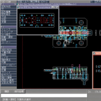
"Hole" with machining attributes
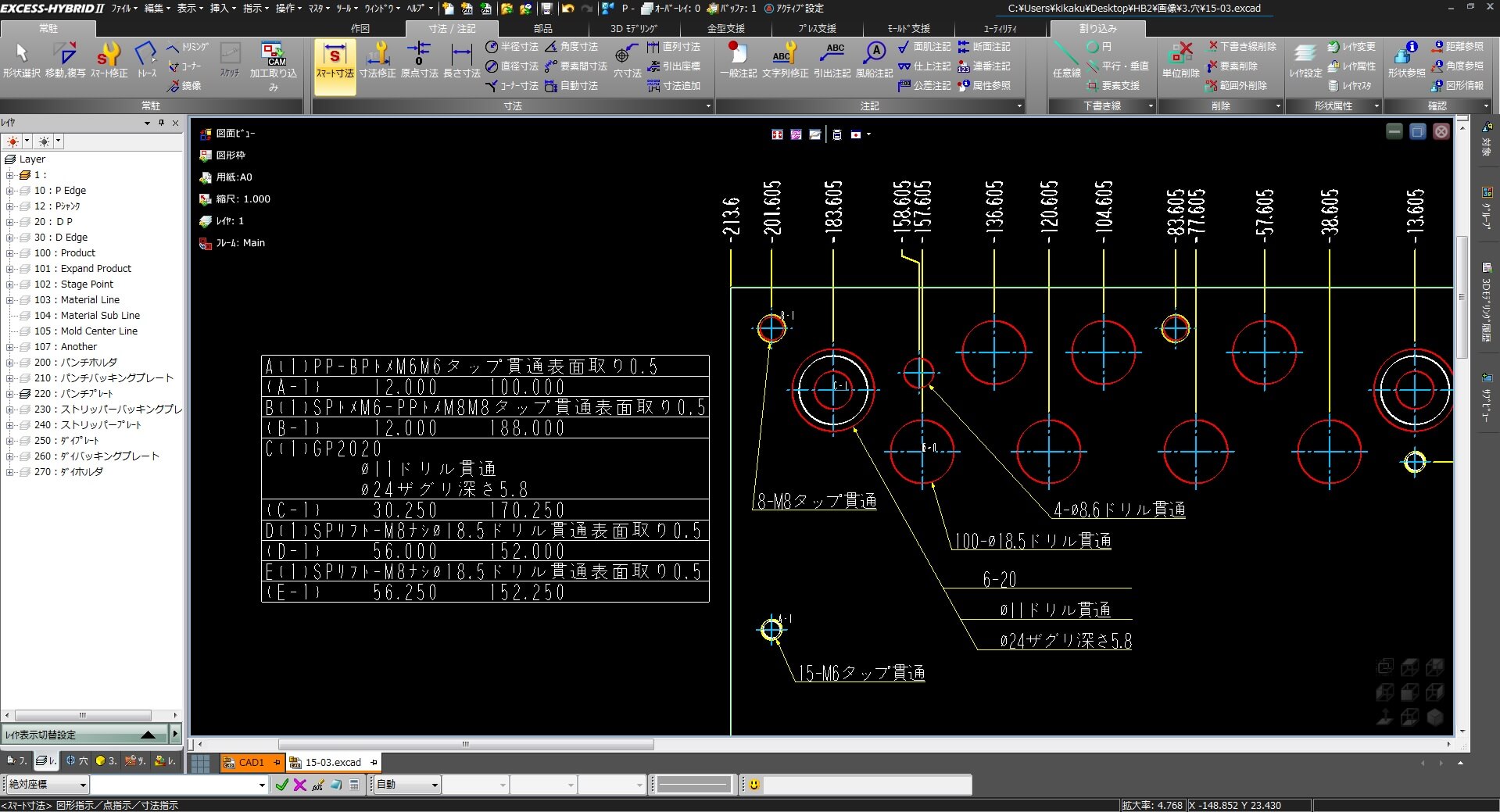
The EXCESS-HYBRID II "hole" is a concept that other CAD systems do not have. It looks like "Circle and Centerline" in the drawing, but it has hole attributes. Attributes are associated with machining types (Drill, reamer, tap, WC, etc.), machining codes (machining process), penetrations, tolerances, etc. Once the mold is designed, machining data can be created with few operations in CAM. You can place "hole" geometry in a normal drawing, but you can also automatically place "holes" with attributes by placing registered standard parts. With additional attributes, "holes" can be used to quickly create hole sections and hole lists in conjunction with multiple plates, which is an effective feature for completing drawings without effort.
Also, when multiple "holes" of the same center are placed, it can be recognized as concentric holes, and machining data can be automatically created on construction of efficient machining process.
In this way, the "Hole" function provides the unique design support of EXCESS-HYBRID II, enabling efficient operation of the entire CAD/CAM system, from hole placement and cross section creation to hole list creation and machining data creation.
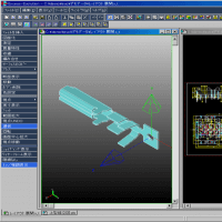
Equipped with advanced 3D modeling function
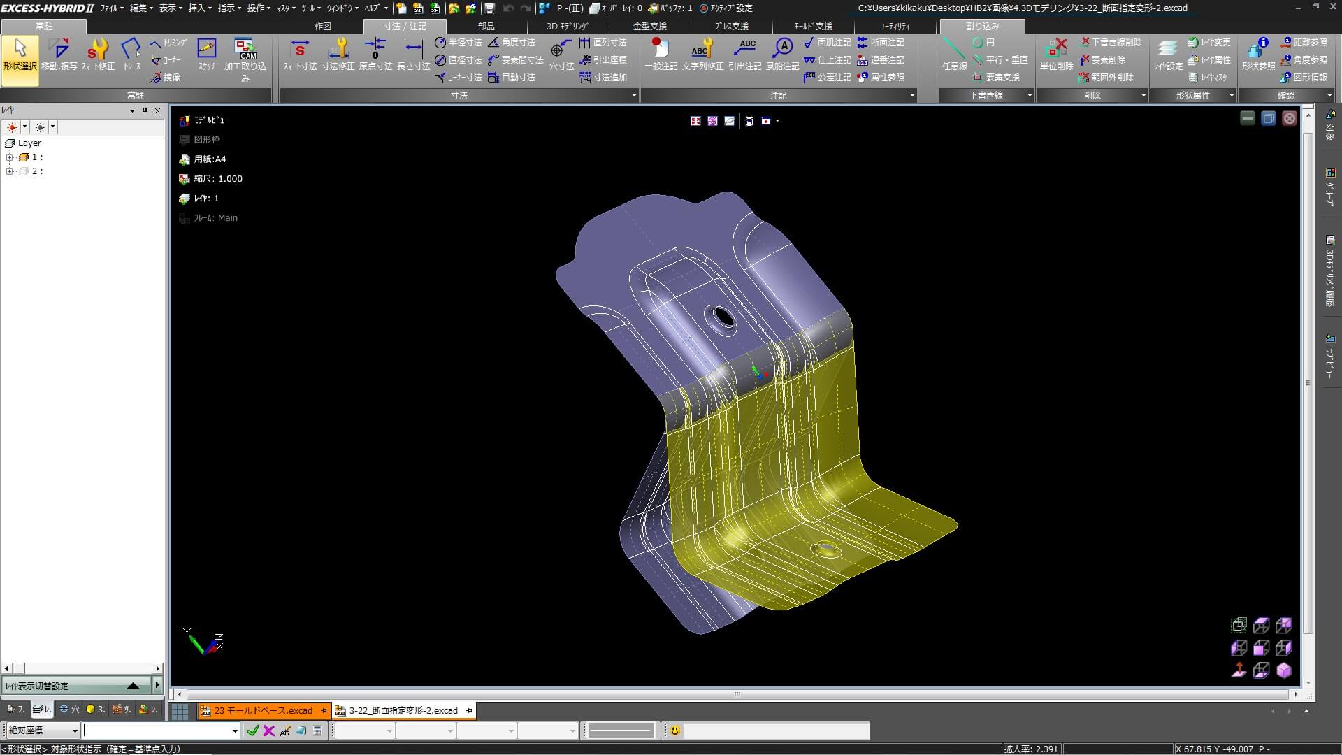
EXCESS-HYBRIDII is not derived from 2D CAD, but provides 3D modeling commands with full historical capabilities. Our unique hybrid technology enables you to work in two and 3D on the same screen and in the same operating system. It includes solid modeling capabilities such as extrude, revolve, and cut, as well as a variety of surfacing capabilities required to create a mold model from a product shape model.
Unlike the conventional EXCESS series, the EXCESS series offers many powerful features that enable the operator to deform the model without feeling uncomfortable, such as the 3D Curve command to create or modify a curved surface, the Create Curved Surface command to modify a curved surface, the Undercut Face check or the Create Draft Face function to create a plastic mold model, the Fill function, the Unfold function to allow spring back to create a press mold model, and the Likely Deformation function to allow the operator to deform the unfolded surface.
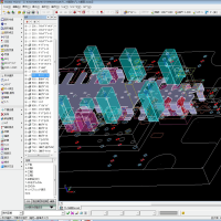
Mold & Die design function
Product data is now supplied in 3D, as is natural. Now that 3D data exists, why not use it to improve design efficiency?
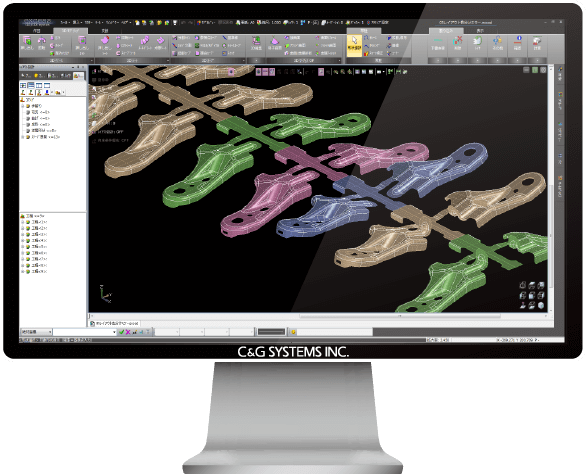
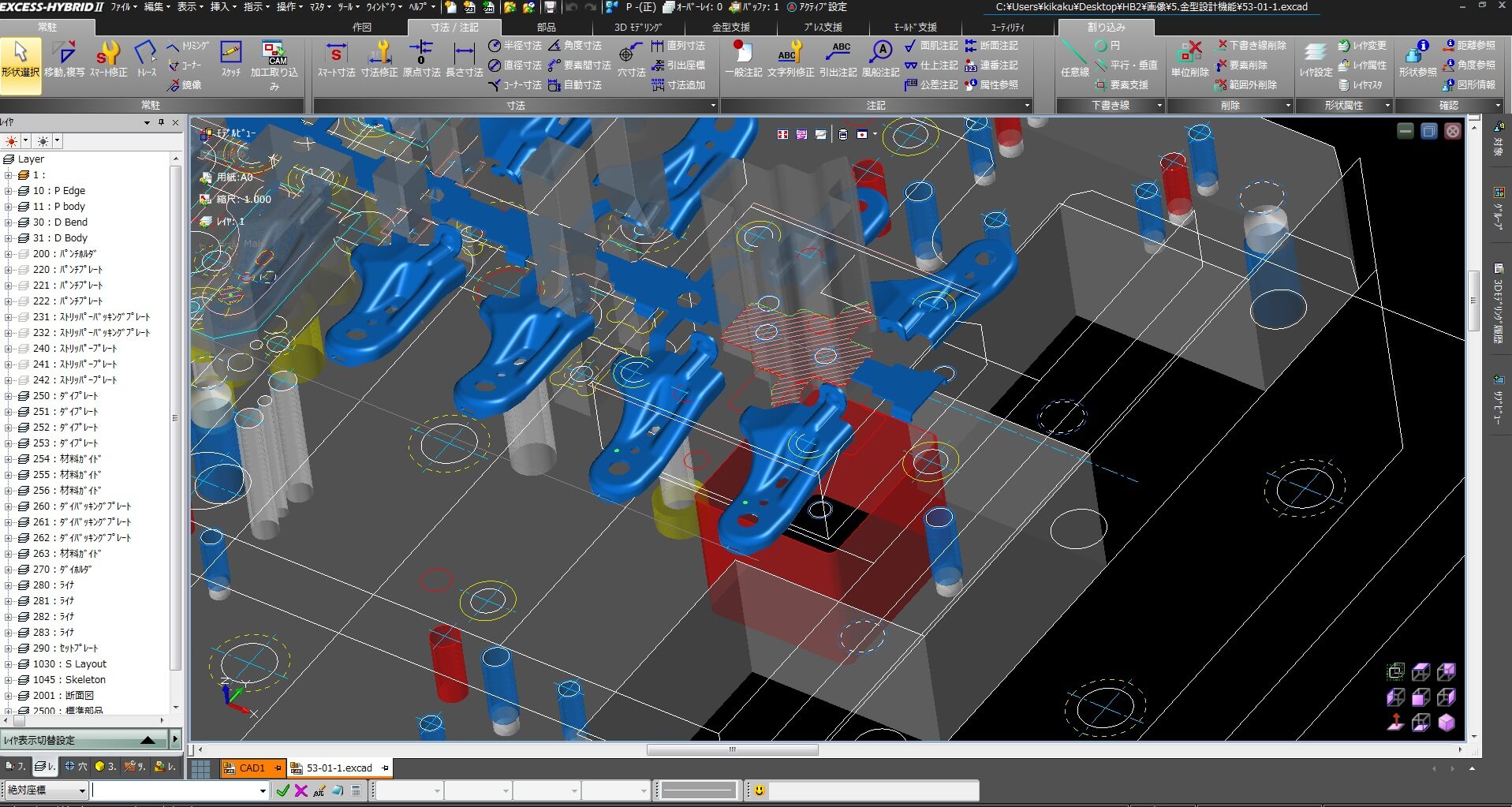
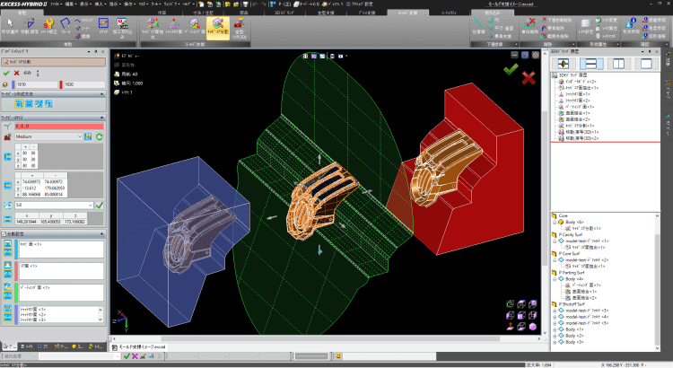
3D design function is installed for layout design of progressive die design. A series of designs such as product shape recognition, bending development, process creation, cutting edge creation and matching, stage development, and intermediate shape capture can be carried out utilizing 3D visibility. In addition, in plastic mold design, 3D design functions such as cavity core surface extraction, parting surface creation and cavity core splitting are provided for cavity core design.
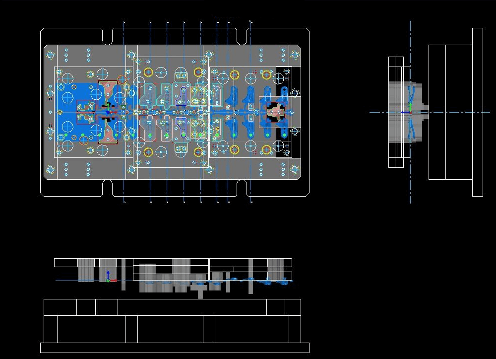
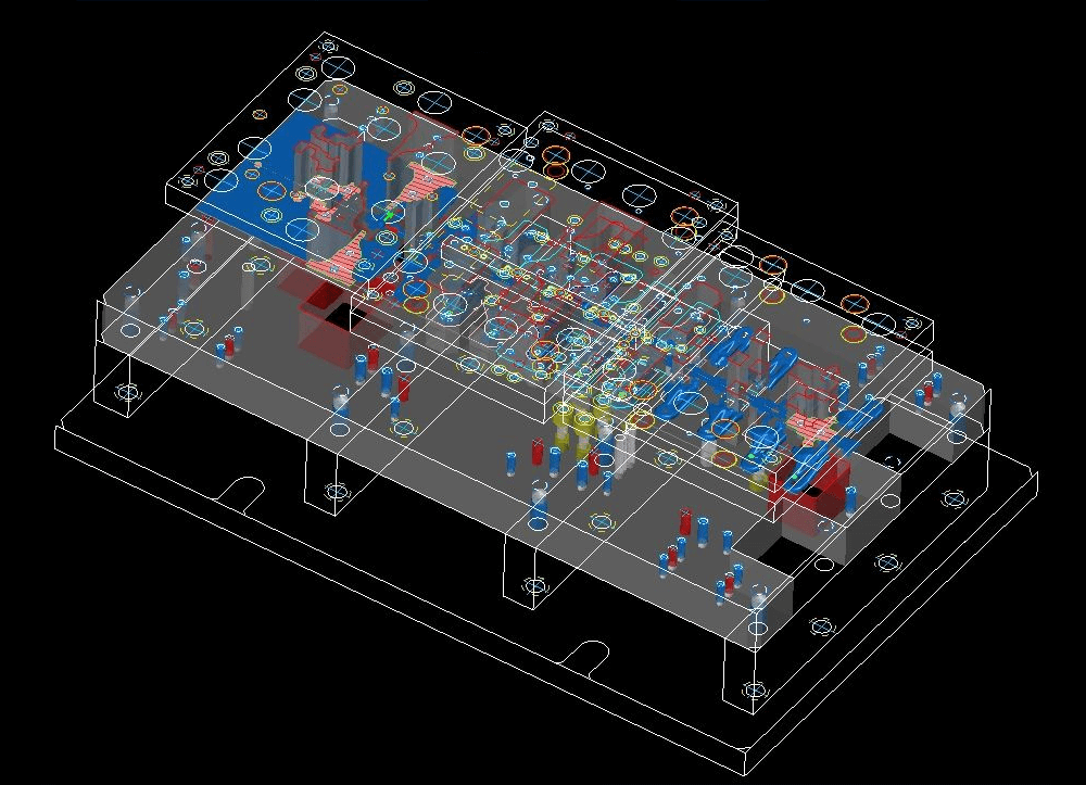
In the mold structure design, it is necessary to arrange all the parts and to operate them in a large amount if it is carried out in 3D, and there is a possibility that the number of parts increases and the performance as CAD deteriorates. By utilizing the advantages of 2D CAD rather than full 3D design, and by using notes and lists instead of drawing, it is possible to realize "More accurate in 3D design, faster in 2D design" through hybrid design in which design work is efficiently performed. Of course, it is equipped with press/plastic mold parts of MISUMI Group Inc. and mold base parts of FUTABA CORPORATION and Nippon Mold Material Co., Ltd. as standard, and it is possible to easily arrange commercially available parts.
Another feature is the ability to separate parts using layers, which makes it possible to complete a part drawing without requiring a lot of work to develop it from a assembly drawing to a part drawing.
Machining data creation by highly efficient CAD / CAM integrated type
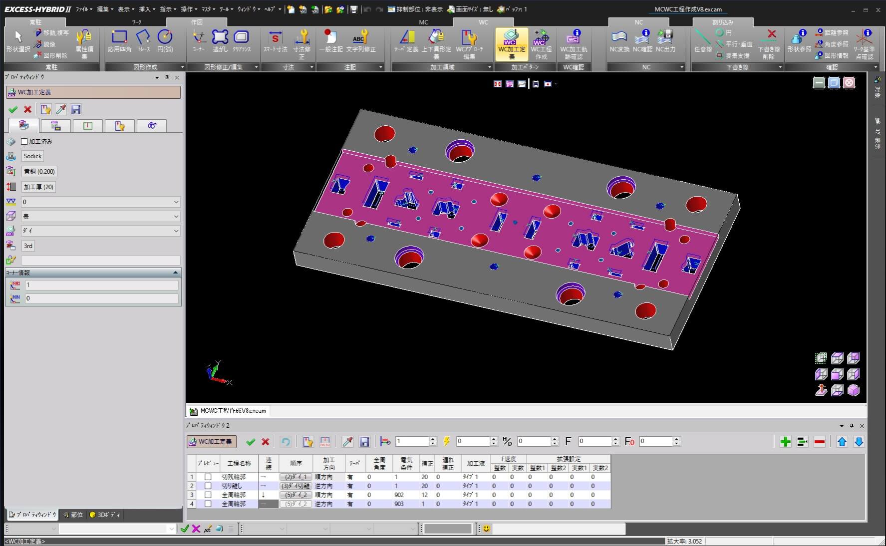
In the EXCESS-HYBRIDII CAD mold design, attributes are added to each part and shape. In particular, the "hole" has a machining code attribute that allows the machining process to be automatically deployed by referring to the master from the machining code as it moves to CAM. It is not necessary to allocate machining processes to each machining location on the CAM side. Machining data can be created easily and the machine tool can be moved quickly. Plate machining with a large number of "holes" in particular can be performed efficiently, such as round holes in machining and deformed holes in pocketing and wire cutting.
It also provides functions such as the ability to receive geometric data from other companies' CAD and create machining data with the attribute of "Hole" by converting from circle to hole, and the ability to automatically add hole attributes to the colored holes based on rules in the 3D model, enabling you to efficiently create machining data from business partners' data. The geometry with the "hole" attribute mentioned above is a feature of CAD/CAM integration.
System Configuration & Requirements
Module configuration for easy system expansion
Module configuration
System expansion is available to meet user's business demand even after introduction. We also welcome customization for specific needs.

Main Module
Base module of EXCESS-HYBRID II enables you to confirm information such as draft and thickness analysis, and to create simple dimensions and annotations by taking 2D figure and 3D model.
Learn MoreIn addition to basic 2D drawing functions, it is also possible to create 2D section view and 2D drawing from 3D model. Abundant output functions are also available such as batch drawing release, batch file format conversion, etc.
Learn MoreAbundant command group is prepared to support Press Die & Mold design, which allows you to call standard parts, to create parts list, and to make an auto-release from assembly to parts drawing.
Learn MoreModeling (Solid & Surface) function allows you to edit figures in consideration of requirements for Molds/Dies. As for surface, uniquely-developed functions superior in peculiar shape processing of dies are available.
Learn MoreCAD Option Module
Deformation of free curved surface such as drawing shape is troublesome and time-consuming task with multiple modeling commands. It requires a lot of modeling skill. Prospective Deformation such as "Matching Deformation" and "Rotation Deformation" will help you change and modify shape by a single command for different purposes.
Learn MoreFlange and shaping parts of drawing figure can be developed as a whole or partially. Trim Development powered by JSOL analysis engine "SOLVER" makes it possible to develop and change the shape of surface model.
Learn MoreBending can be developed as a whole or partially to create a blank figure quickly. Development of shaping figure such as forced bending and flange with bead and crushing has become available.
Learn MoreSpringback and prospective surfaces, once experience and modeling skills are required, can be created easily.
Learn MoreSupport functions for drawing parts as well as for Press Die design by 3D model are available. It is also possible to customize according to user's own design rules.
Learn MoreSupport functions for drawing parts as well as for Mold design by 3D model are available. It is also possible to customize according to user's own design rules.
Learn MoreIt is possible to perform advanced conversion that can not be obtained by IGES or STEP conversion.
CAM Option Module
Process functions for Machining are available. High quality machining data from 2D/3D data can be created by abundant machining patterns and post processor that can be flexibly customized.
Learn More
Die/Mold core parts such as punch dies and cavity cores can be processed with high quality and high efficiency.
Includes a 3D Rough machining mode (Z-level Rough Cutting / Scanning-line Rough Cutting).
Die/Mold core parts such as punch dies and cavity cores can be processed with high quality and high efficiency.
Includes a 3D finish machining mode (Z-level Finishing / Scanning-line Finishing / Rest / Along Surface / Curve).
Die/Mold core parts such as punch dies and cavity cores can be processed with high quality and high efficiency.
Includes a 3D finish machining mode (Horizontal Area Cutting / Curve Control Along Surface / Corner Processing / Pencil Cutting).
Toolpath confirmation, information display, and editing functions such as path deletion and copying are provided.
Learn MoreProcess functions for Wire-cutting are available. High quality Wire-cutting data from 2D/3D data can be created by abundant machining patterns and post processor that can be flexibly customized.
Learn MoreIt generates machining programs for CNC lathes, including roughing, finishing, grooving, threading, parting, and boring operations. When combined with MC functions, it enables process consolidation using multi-tasking machines.。
Learn MoreSystem requirements
OS |
Windows 11 Pro / Windows 11 Pro for Workstations / Windows 11 Pro Education |
CPU |
Multi-Core Processor |
RAM |
8GB or more |
HDD |
80GB or more |
VIDEO |
3D Acceleration OpenGL board(NVIDIA® RTX / Quadro) |
NEW Function of EXCESS-HYBRIDⅡ
Version Up Information
Version11.1 Released on Feb.2026
Turn Client Drawings into Your Specs in No Time !
Slash Path Programming Time & Cut Down Tool Load !
- Hole Convert
- Change Layer No.
- DXF/DWG Input・Output
- Annotation CSV Output
- Same Shape Search
- Leyer Release
- Wrap
- Boundary Fitting
- Corner Smoothing
- Corner R Processing
Process Integration for Turning & Milling on Multi-Tasking Machines
- Turning Process
- Milling
- B-axis indexing
- Grooving
- Treading
- Machine Simuration
- Machin and Machining Pattern Setting
etc. - Learn More


Version10.1 Released on Feb.2025
Enhance Work Efficiency with Improved File Management, Drawing, and Verification Functions!
Reduce Machining Time with Deburring Features and Optimized Toolpaths!
- File Selector
- Fillet/Chamfer
- Deburring Curve
- Curvature
- Work Coordinate System
- Protruding Length/ Under head Length
- Z-level Rough Cutting
- Spherical tool
- Deburring Machining
- XY/Z Allowance etc.


Version9.1 Released on Feb.2024
Easy Search for Similar Body Using Historical Data!!
Cylinder and Polar Coordinate Interpolation for Expanding the Machining Range!!
- AI Search Similar Bodies
- Hole list
- Free form
- Repair Mesh
- Catalog Holder
- Cylindrical Interpolation/Polar Coordinate Interpolation
- MC Approach Settings
- WC Approach Settings
- Z-level Line Finishing
- Curve etc.
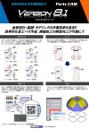
Version8.1 Released on Feb.2023
Pursuing efficiency in mold design, drawing, and modeling !!
Possible to create efficient machining paths and improve precision in fine machining !!
- Offset(Corner Escape mode/Custom mode)
- Corner(Continuous R)
- General Annotation (QR codes)
- Trim(selecting sketches)
- Out cut(New path type)
- 2D Optimization
- Scale Calculation
- Tooling Catalog
- Stock Comparison
- WC Batch Prehole *QR Code is a registered trademark of DENSO WAVE INCORPORATED.
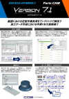
Version7.1 Released on Mar.2022
Eliminate workloads for drawings with one click!!
Drastically reduced rework of creating machining data !!
- Replace All Annotations
- MISUMI Order
- Figured Characters
- Frame(Exporting multiple DXF files)
- For 3+2 Machining (Profile/ Auto Area Extraction)
- MC Machining Definition
- MC Process Creation / Edit
- WC Process Creation
- Modeling
- 3D Machining Definition etc.
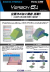
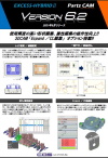
Version6.1 / 6.2 Released on Feb.2021 / Aug.2021
New Functions For 3+2 Machining !!
Significantly reduces CAM operation time and set-up time !!
- MC:3+2 Machining
- MC : Auto Area Extraction
- MC : Compatible machine
- MC Process Creation
- Define Open Surface
- Edit THD
- Finish Option(New machining mode) etc.
Improved operability of drawing / attribute editing!!
3DCAM "Expand / Edit CL" added as options !!
- Change Layer No. / Change Line Type
- Batch Prehole / Parts Release
- Body Attribute
- Edit Fillet / Hole Dia.
- MC: Retract
- MC: Multiple times machining for open profiles
- MC:Viewpoint
- WC:Cut off in two steps (Die)
- New optional modules
"Expand / Edit CL"
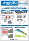
Version5.1 Released on Feb.2020
The interlocking between frames reflects the adaption of the assembly and its part drawings.
3D CAM expands the range from plate processing to die processing.
- Flame ( Interaction / Save )
- Spring Graph
- Fill function enhancement
- Edge matching function enhancement
- Feed control of the zigzag machined part
- 3D CAM "Rough" Module
- 3D CAM "Finish" Module
V5.1 Digest Movie (Japanese)
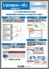
Version4.1 / 4.2 Released on Feb.2019 / Sep.2019
Pursue further Hybrid design efficiency Standardization of design work, Create an efficient processing path, modeling feature enhancement !!
- Set range to parts & layer numbers
- Frame function
- Bend Table Extension
- Hole Part No. Setting
- Checking Undercut
- Section Specified Deformation
- G01 Cycle
- Swing Deformation
- MC Simulation Enhancement(V3.3)
- WC Area Extraction Improvement(V3.3)etc.
- Enhanced drawing-related(V4.2)
- Enhanced 2D CAM(V4.2)
V4.1 Digest Movie
Version3.1 Released on Feb.2018
Further Pursuit of Efficiency in Hybrid Design for Design/Drafting/Machining Work Supporting Global Design by UNICODE !!
- Document Tab
- UNICODE Support
- Partition / Change Part Group
- Shape Restoration
- 2 Tangent Curved Faces
- Arrow View
- Trim Development
- NC Conversion Check
- Hole : Remaining Value
- MCSimulation Enhancement(V3.3)
- WC Area Extraction Improvement(V3.3)etc.
Version2.1 Released on Feb.2017
Support for upstream mold design data with powerful 3D functions !!
CAM data editing work more efficiently and safely !!
- Input assistance function enhancement
- Geometric Constraint / Automatic addition
- Surface ( Fillet Surface / Join Curved Surface )
- Prospective Deformation enhancement
- Trim Line Development enhancement
- Mold Support / Split cavity and core
- Processing definition / GUI renewal
- Machine Simulation etc.
Version1.1 Released on Dec.2015
EXCESS-HYBRID Renewal - Significant Progress in Design Efficiency!!
Range of application has been greatly expanded, which supports Precision progressive pressed parts, Small drawing parts, Resin parts, etc.
- Ribbon Menu
- Pre-select
- 2D Geometric Constraint / Dimension Constraint
- 3D History Feature
- 2D Standard Parts
- Surface (CAD option)
- Prospective Deformation (CAD option)
- Trim Line Development (CAD option)
- Bending Development (CAD option)
- Layout Support (CAD option) etc.
V1.1 Digest Movie
HISTORY
Inherited DNA - Further Advanced Hybrid System
Since the 1st release of "EXCESS series "in 1986, EXCESS has been growing to reach to be an industry standard, as it could be said that the evolution of EXCESS is the history of the innovation of Mold&Die designing and manufacturing technology. Thanks to the system excellency and the dominant recognition in the market, it is now the top share of 2D CAD/CAM system in Japan.
-
1986
"EXCESS" Released
1988/UNIX Edition
1994/EWS Edition -
1999
"EXCESS-Plus" Released
Windows Edition Released
-
2004
"EXCESS-Evolution" Released
-
2007
"EXCESS-HYBRID" Released
Hybrid System Released
-
NEW!!
EXCESS-HYBRIDⅡ2015
EXCESS-HYBRIDⅡ Released
EXCESS-HYBRID Renewal !!
OTHER PRODUCT

Product Inquiry
Contact us