SYSTEM MODULE CAM
CAM Module(MC/WC/TURNING)
Process functions / Machining & Wire-cutting and Turning

MC(Machining Process)
The unique processing pattern structure enables you to automatically expand design information into processing information, enabling you to create high-grade 2 axis and 2.5 axis processing data from 2D / 3D data.
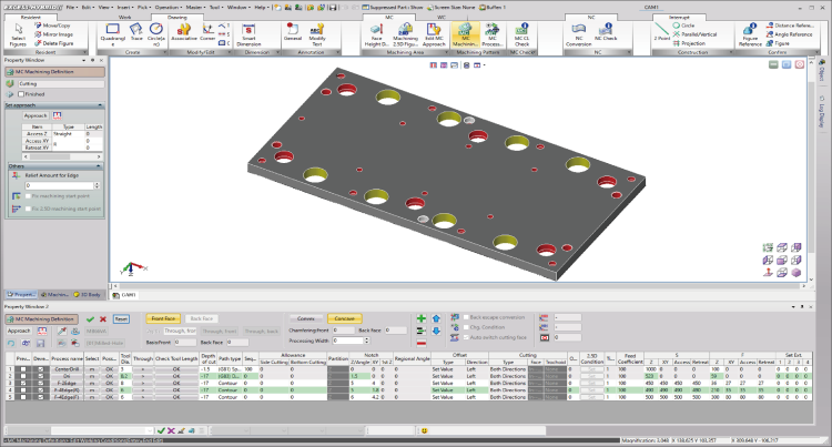
Machining definition
Automatically assigns machining operations to a machining code defined in CAD for a 2 dimensional shape.You can define a machining process by using a list format interface while checking the pre and post process. You can also use a standardized machining pattern to quickly output NC data when you create machining data from an imported drawing, such as DXF.
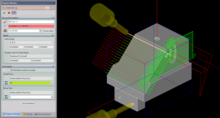
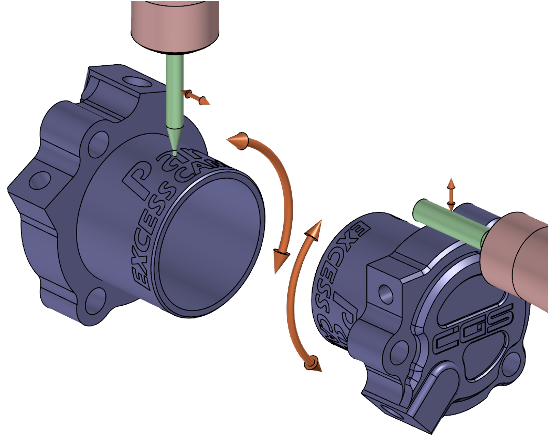
3+2 Machining
By defining the machining axes from any direction, drilling and 3+2 Machining with the workpiece positioned by the tilting and swiveling axes are now possible. NC data for multiple planes can be created at a time, so that the CAM operation time has been greatly reduced, added to the shortened time for setup and changeover and jig machining.
It also supports the output format of NC data such as "Inclined Face Machining Command" and "Convert Coordinate (Fixture Offset Macro)".
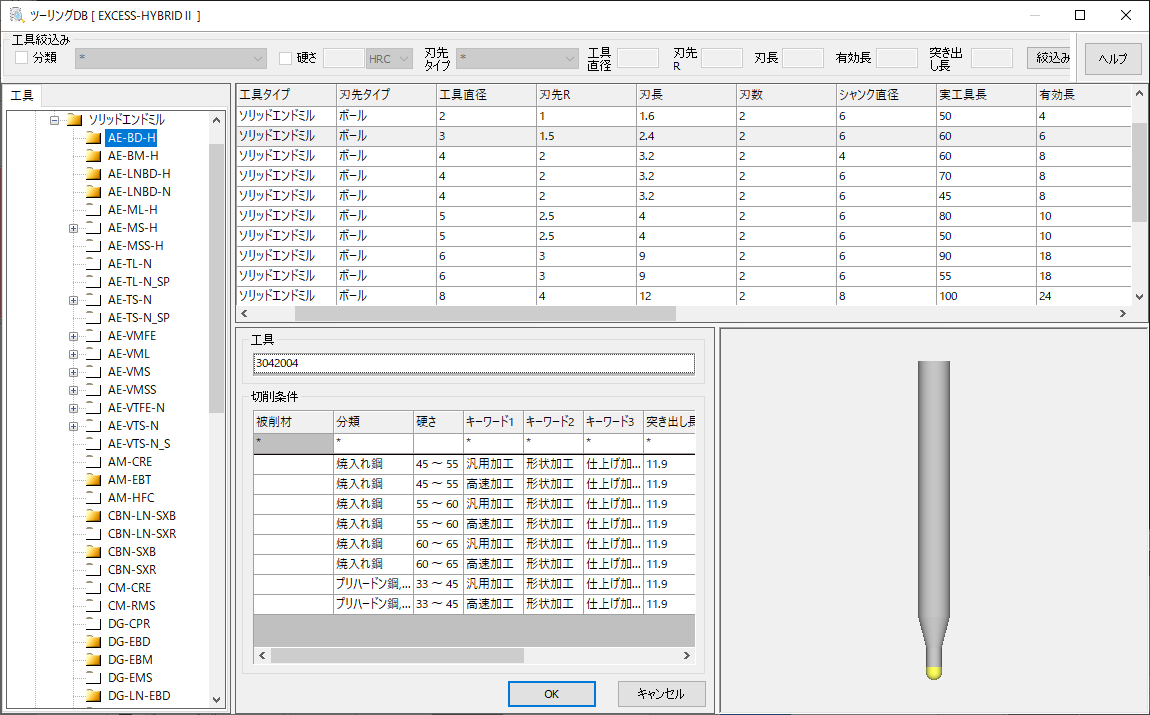
Tooling/Holder Catalogs
Tool and holder catalogs from major japanese manufacturers are available. It is possible to refer to the manufacturer's recommended values for tool parameters and even cutting conditions. Catalog data can be downloaded from the web for easy registration.
Hole/Pocket
You can easily create NC data by automatically expanding the processing attributes given by the designer to the machining process. By standardizing the processing pattern, stable machining data with no variation can be created.
Helical Tapping
In reference to the tool information from the master, NC data according to helical tap tool can be created. It is possible to specify the notch amount of XY to drive the machining area into inside by repeating several times.
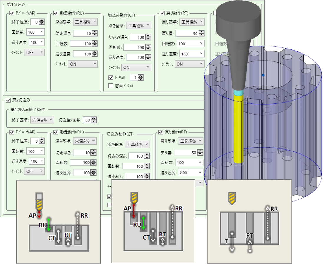
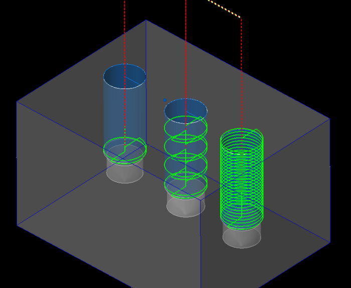
G01 Cycle
You can use G01 code to perform the behavior of a normal fixed cycle.It is possible to define a unique cycle code by mastering the settings such as the cut rate and the return amount at the depth ratio.
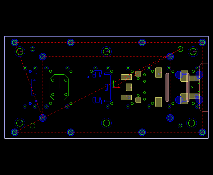
2.5D Machining
2.5D contour line machining of X-Y axis can be easily performed based on the information of plane view and section view. You can also create a 2.5D machining pass in the X-axis and Y-axis direction by performing an axis conversion.
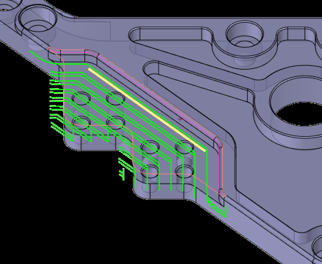
Out cut
Creates a machining path that is offset in any direction relative to the target feature. Can be defined for open or closed shapes. A "stock contour" can be specified to limit the machining area.
Corner Smoothing/Trochoid
Uncut parts by rough machining can be automatically recognized to create a machining path for them with small diameter tool. Trochoid machining path can be created to reduce the load and realize high-speed machining at the points where the load on tools becomes large.
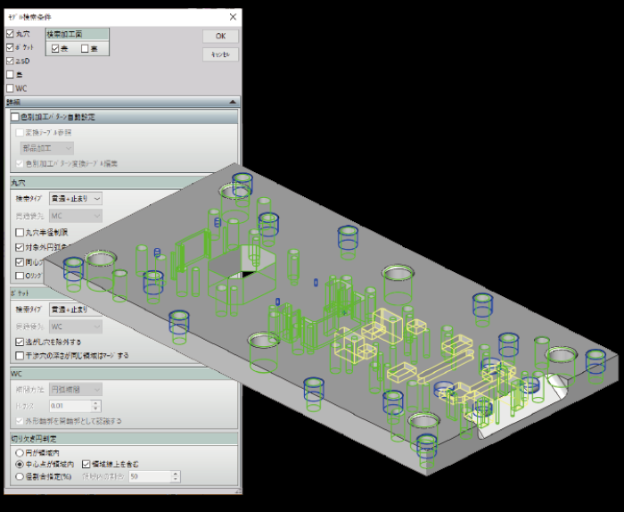
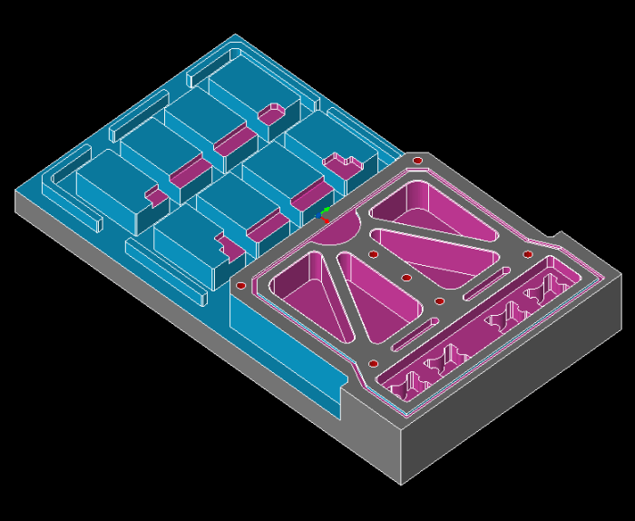
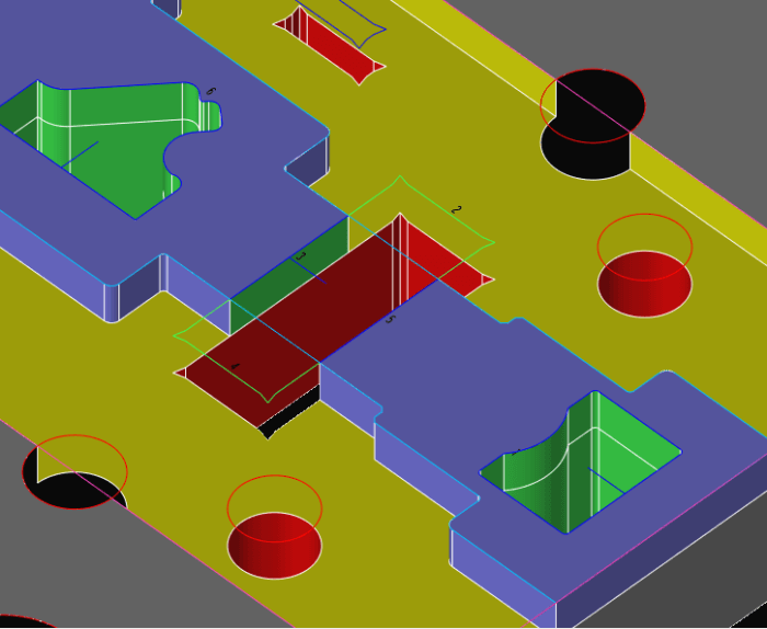
Part extraction
Automatically recognizes a 3D model and automatically creates a round hole, pocket, 2.5D, and island profile. The recognized shape has machining attributes, such as depth and chamfer. If a face color is assigned to a working part of a 3D model, you can also assign a machining pattern at the same time.
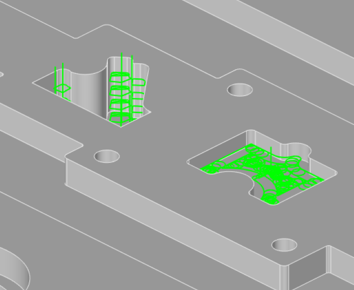
Leaving Island Machining
Multistage path for Island Left Machining can be automatically created by applying the height from the machining face to the island shape in machining area.
Specify Finished Work
By defining multiple machined areas, you can create a secondary machining pass without waste. In addition, it is also possible to form a 3D plate that recognizes the machined area, which can be used for MC simulation and confirmation work.
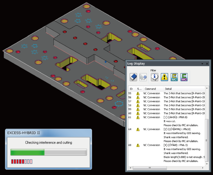
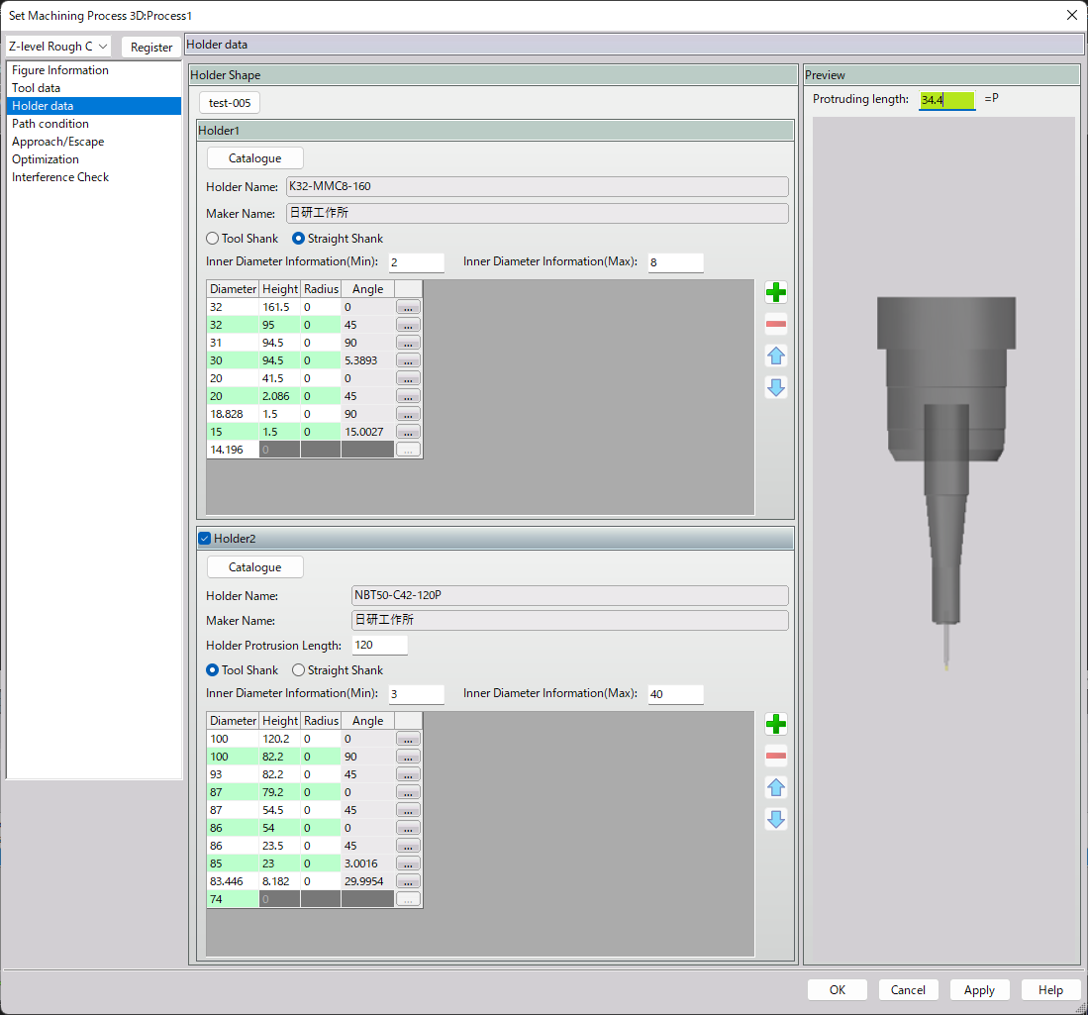
Check Interference / Cutting
During NC conversion, the interference of the shank and the holder is checked, and the problem points are output to the error log.In addition, the NC output command, which is the final stage of the CAM operation, is displayed as a warning, so the NC data can be detected before the actual processing can be detected.
Cylindrical Interpolation / Polar Coordinate Interpolation NEW
The functions of cylindrical and polar interpolation enable cutting operations utilizing the rotation axis. Cylindrical interpolation generates a path on a plane wrapped around a cylinder, while polar interpolation creates a path for drilling or milling, synchronizing the rotation axis with one of the other axes.
MC Option (Rough / Finish / Expand /CL Editor)
This is a 3-axis CAM option with toolpath generator that was developed with the rich processing experience of "CAM-TOOL". The mold core parts such as punch die and cavity core can be processed with high quality and high efficiency.
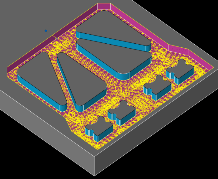
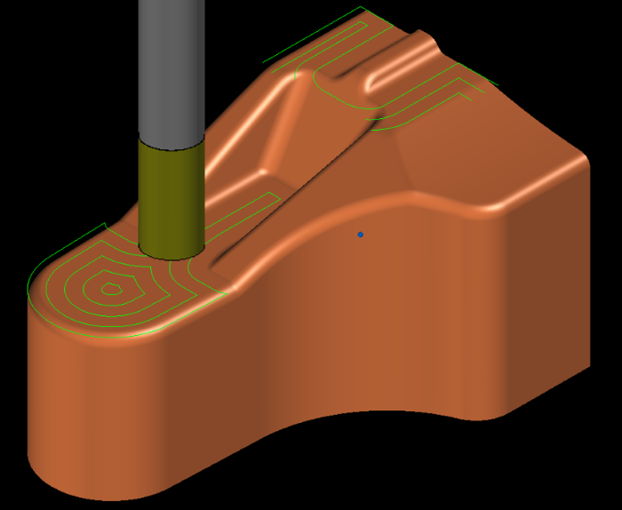
Z-level Rough Cutting Rough module
Create Z-level offset tool-paths for roughing. You can create a high efficiency path by referring to the stock of the previous process, and a low load path by connecting a trochoid or a corner R.
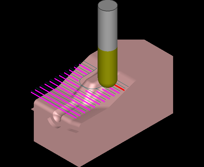
Scanning-line Rough Cutting Rough module
Creates a roughing path by a Z-level constant reciprocating operation.Machining by a reciprocating line leads to a reduction in machining time due to the reduction of connection movement. The system automatically determines the cutting area for the composite shape to create an efficient path.
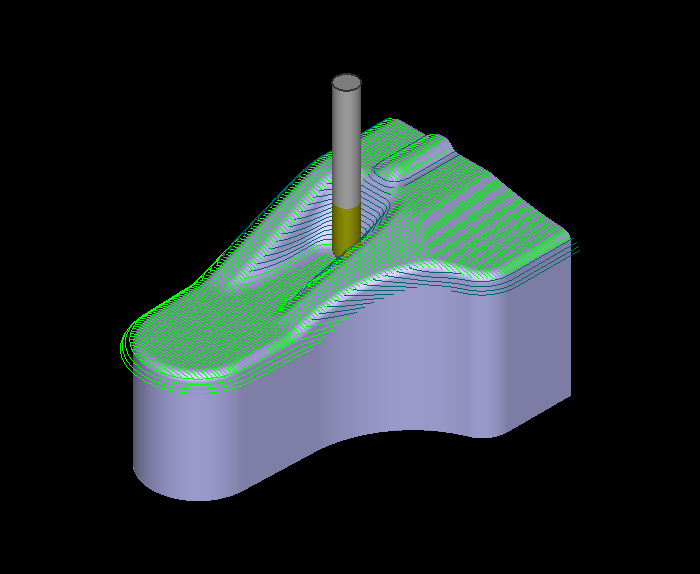
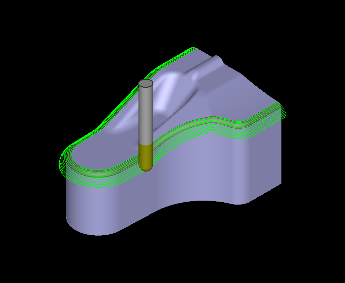
Z-level Finishing Finish module
"Z-level Finishing", which performs climb milling, assures quality high speed and high-precision machining. Spiral tool-paths can be also created, which contributes to the reduction of connecting-moves. This is the best way to machine automatically since gently sloping area and horizontal area can be also executed at once.
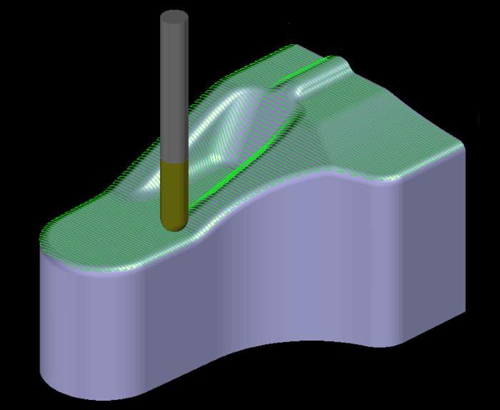
Scanning-line FinishingFinish module
The area where the Incline angle of the specified shape is less than or equal to the specified angle is determined to be the machining area, and the Scanning-line path is created.
There are four Traveling types : "Scanning one way", "Scanning zig zag", "Open offset path“ and "Closed offset path". These are meant for the optimum machining methods according to the shape and cutting conditions.
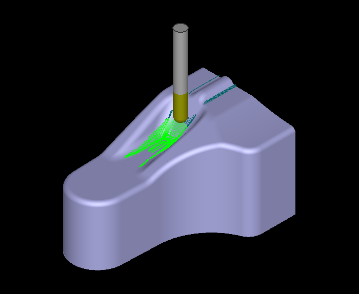
Rest Finish module
The system automatically detects the uncut area of previous process, and generates tool-paths for the remains. It is possible to machine efficiently for each portion, cutting by along-surface tool-paths at gently sloping area, and cutting by Z-level tool-paths at steep and groove area. The uncut area can be recognized correctly since any types of cutting-tool (ball/radius/square end-mill) can be utilized.
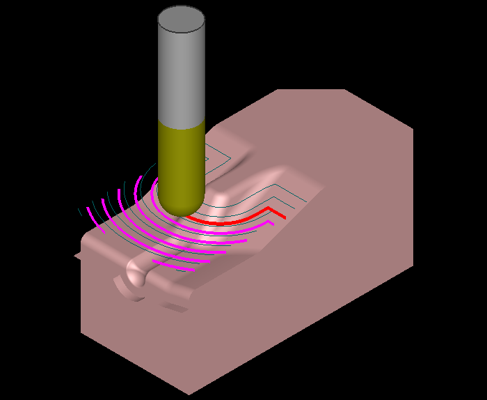
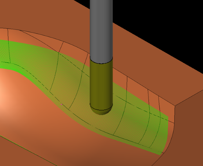
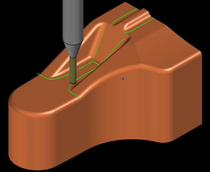
Along Surface Finish module
Creates a machining path with a constant pitch along the face. Paths that interfere with the shape can be projected in the direction suitable for the shape.
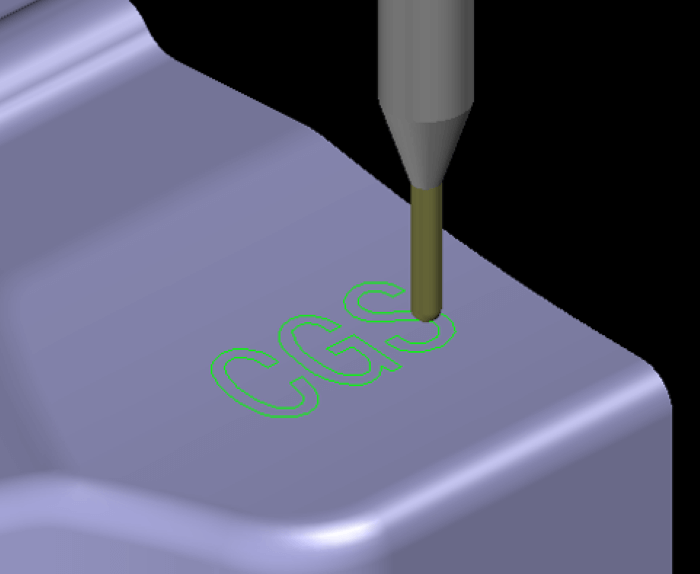
CurveFinish module
Creates a machining path centering the tool along 3D curves. This mode is also suitable for Z Driving machining, slot machining and text engraving.
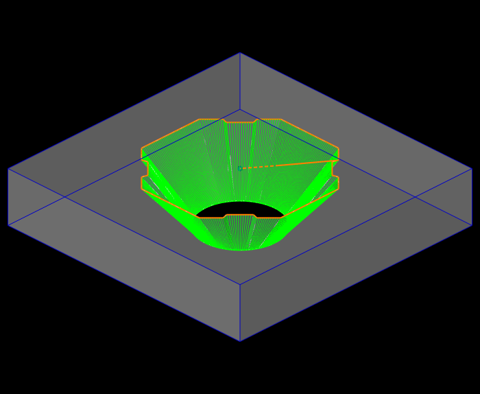
Horizontal Area Expand Module
The system automatically extracts horizontal area and generates offset around paths with down cut. This mode is useful for cutting flat area with radius and flat end mill.
Along Compound Side Expand Module
This mode cuts along 3 dimensional surfaces within the closed area enclosed by contours. U/V of surfaces don't affect the cutter paths. Air-cut can be reduced especially for a large metal mold.

Cornering Expand Module
Creating tool-paths for concave ridge-line area with smaller cutting tool. It can reduce fluctuation because cutting direction is automatically controlled according to the angle of the ridge-line.
Pencil Expand Module
Radius and flat end-mill can be used for pencil cutting as well as ball end mill. Tool-paths are created along the edge-line which is automatically extracted.
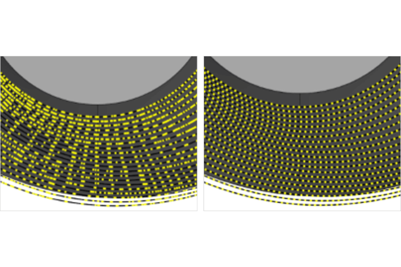
Path Calculation Logic
The general CAM system converts the received data (IGES, etc.) into approximate polygons, and performs CAM operation. However, the "MC Option" is a CAM solver that is developed with a rich processing performance of "CAM-TOOL". The CAM solver is equipped with a unique "Surface calculation" that allows the tool to contact the curved surface of the CAM, and achieves smooth processing and precision.
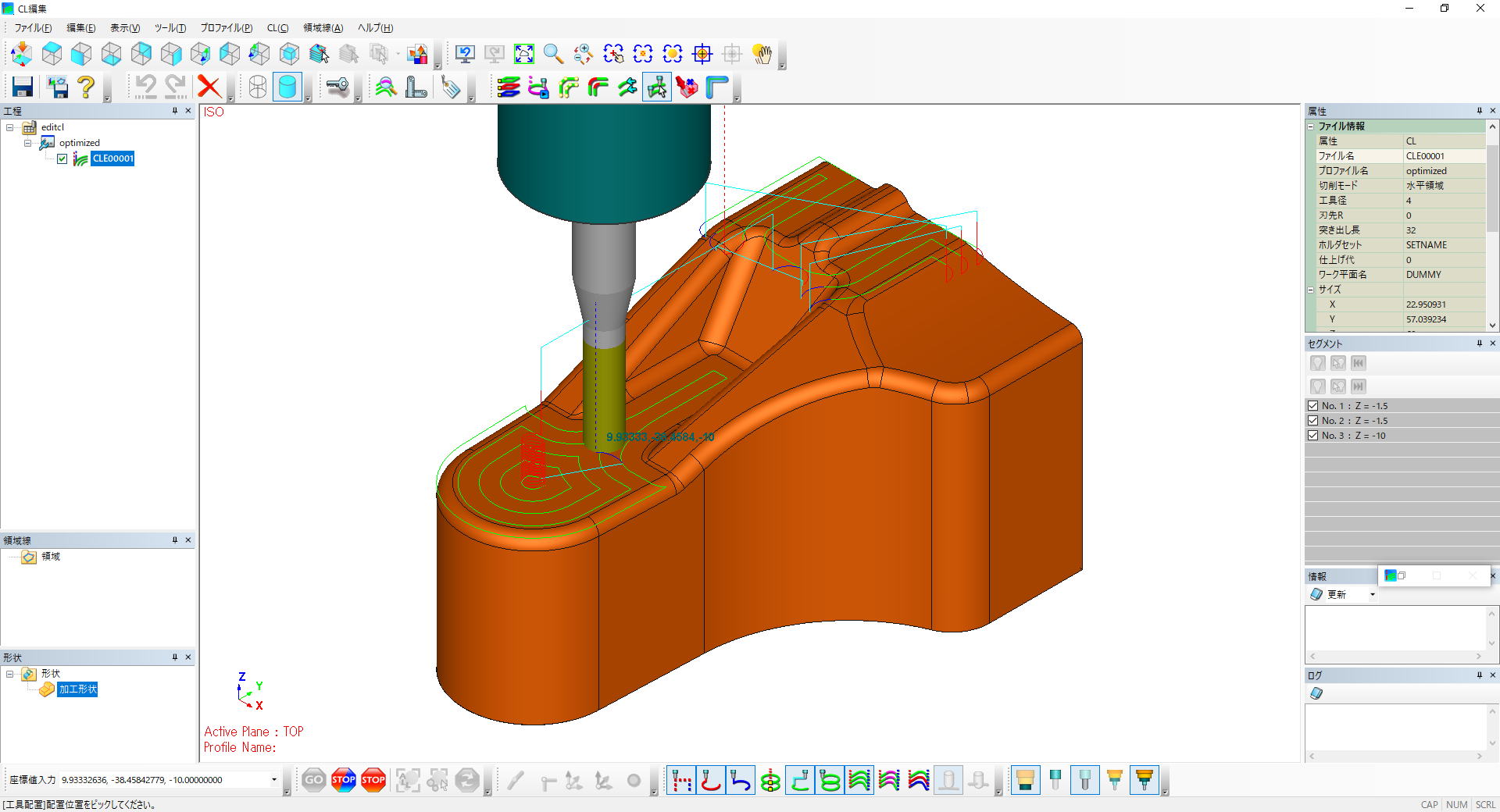
CL Editor CL Editor Module
CL Editor CL Editor Module
In addition to confirming the path of the tool path and displaying information, you can edit the selected path by deleting, copying, etc., and change the feed speed, making use of the customer's know-how for advanced editing.
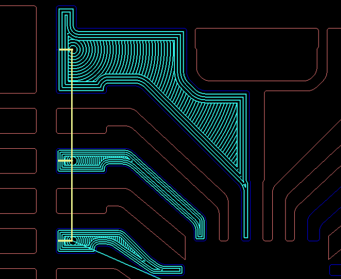
WC(Wire-cutting Process)
This is a CAM option for wire discharge machining. Machining data can be created by assigning rich processing patterns and processing conditions such as punch, die, 4-axis Machining, coreless, and so on. It also supports new machine tools such as Welding Machining, and can improve the operating efficiency of machine tools and the efficiency of work.
4-Axis
NC data for machining with different profile between top and bottom can be automatically created by specifying the figure of program/sub-program face. It is also possible to define the profiles from 3D models.
Coreless Machining
Coreless machining for round/deformed holes can be performed. Gradually-changed taper machining is also supported in coreless machining. The long unmanned operation of machine tool becomes possible because cutoff figure does not occur, which contributes to the improvement in machine operating rate.
Step Machining
Wire cutting conditions can be set separately at the sections where the thickness changes, which allows you to create NC data that considers disconnection and reduction of machining failure. You can confirm, change, and delete the conditions easily.
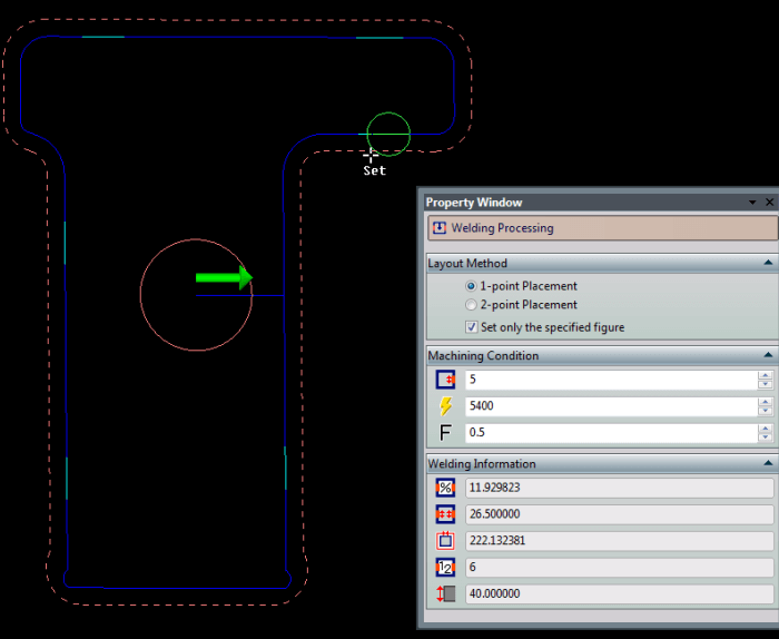
Welding Machining
It is often necessary to rely on human hands for the removal of cores in plate processing. It is a function to eliminate the cutoff process by welding the core partially in machining. We can save labor by cutting off the separation process.
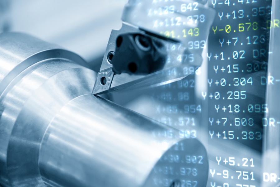
TURNING NEW!!
It generates machining programs for CNC lathes, including roughing, finishing, grooving, threading, parting, and boring operations. When combined with MC functions, it enables process consolidation using multi-tasking machines.
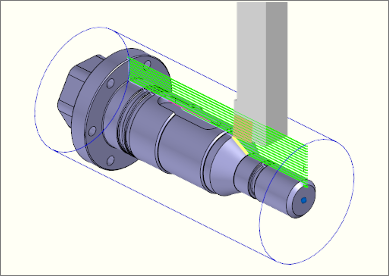
Turning Process
Programs for NC lathe operations such as roughing, finishing, grooving, threading, parting, and boring can be easily created through intuitive operations.
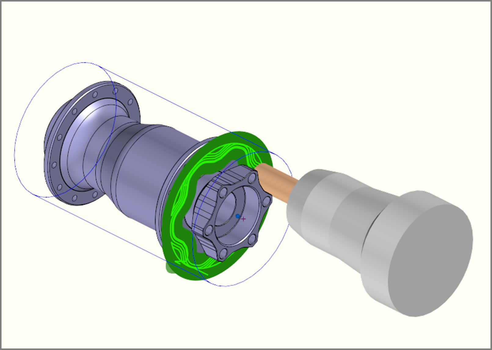
Milling
When combined with the MC license, milling programs such as drilling, pocketing, slotting, and chamfering can be created with the same familiar operability as before.
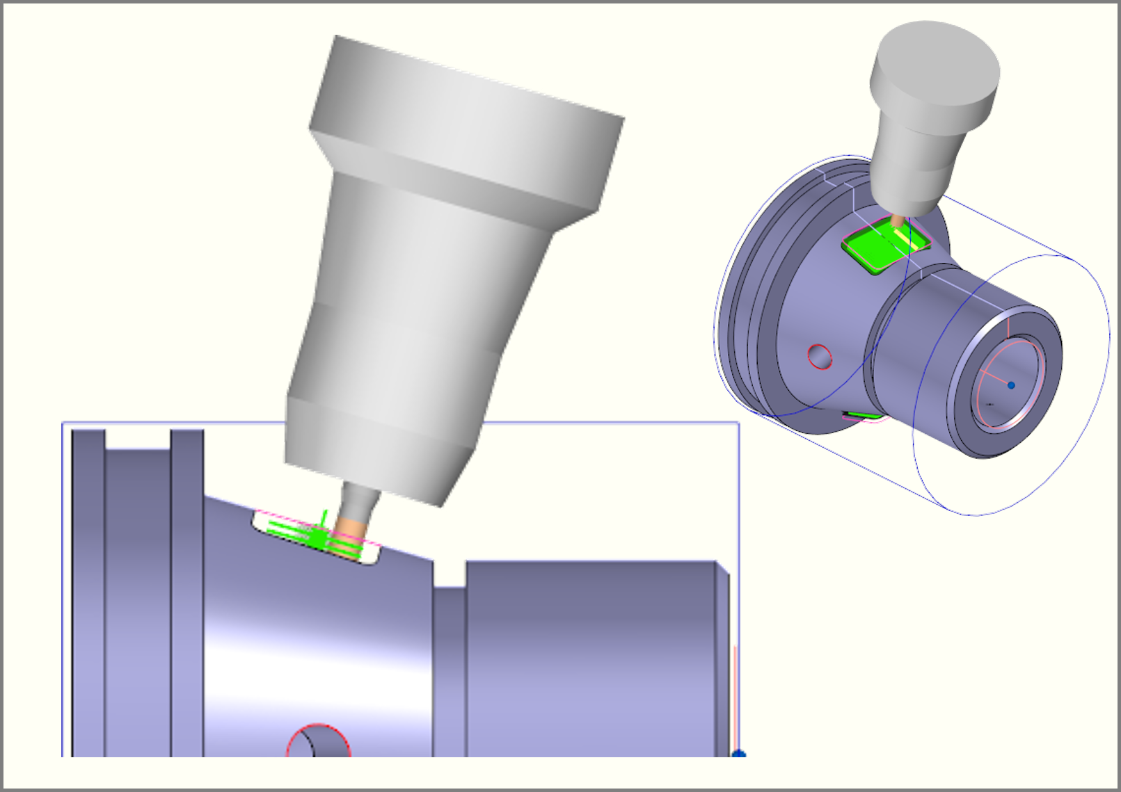
B-axis indexing
Indexing programs using the B-axis can be created. Programs for polar coordinate interpolation (XC-axis machining) on end faces and cylindrical interpolation (ZC-axis machining) on side surfaces are also supported.
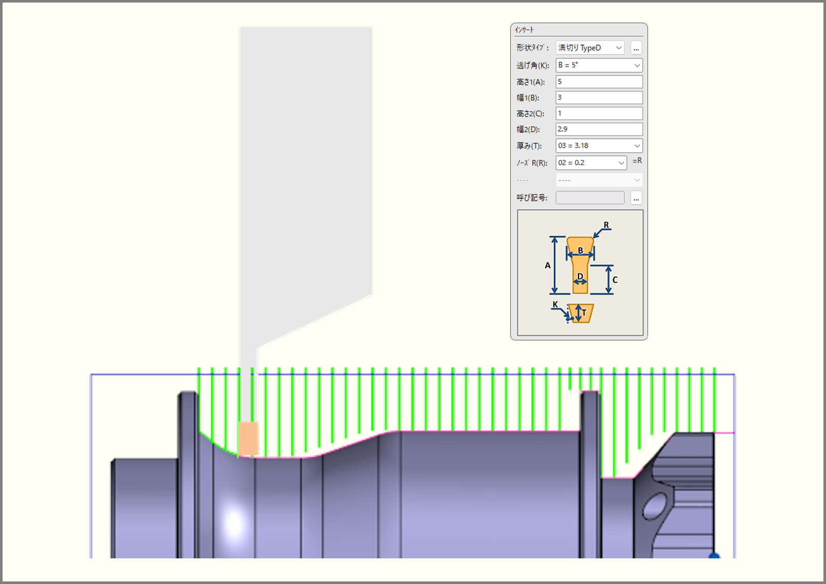
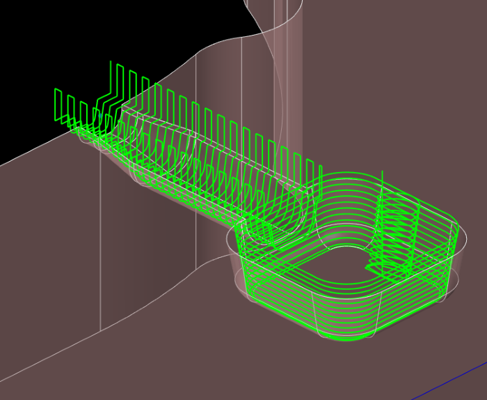
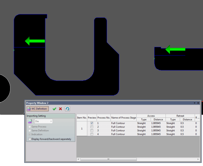
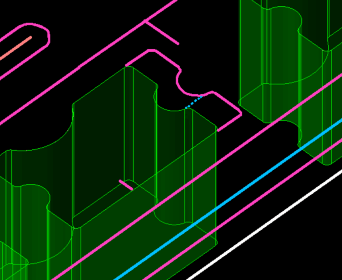
Grooving
Grooving operations for complex shapes, including curved surfaces, are supported. Functions such as segmented peck cutting for effective chip control, dwell at the groove bottom, and back-off movements are also available.

Threading
The depth of cut for threading can be selected between constant depth and constant cutting load. Cutting methods including both-flank cutting, single-flank cutting, and alternate-flank (zigzag) cutting are available.
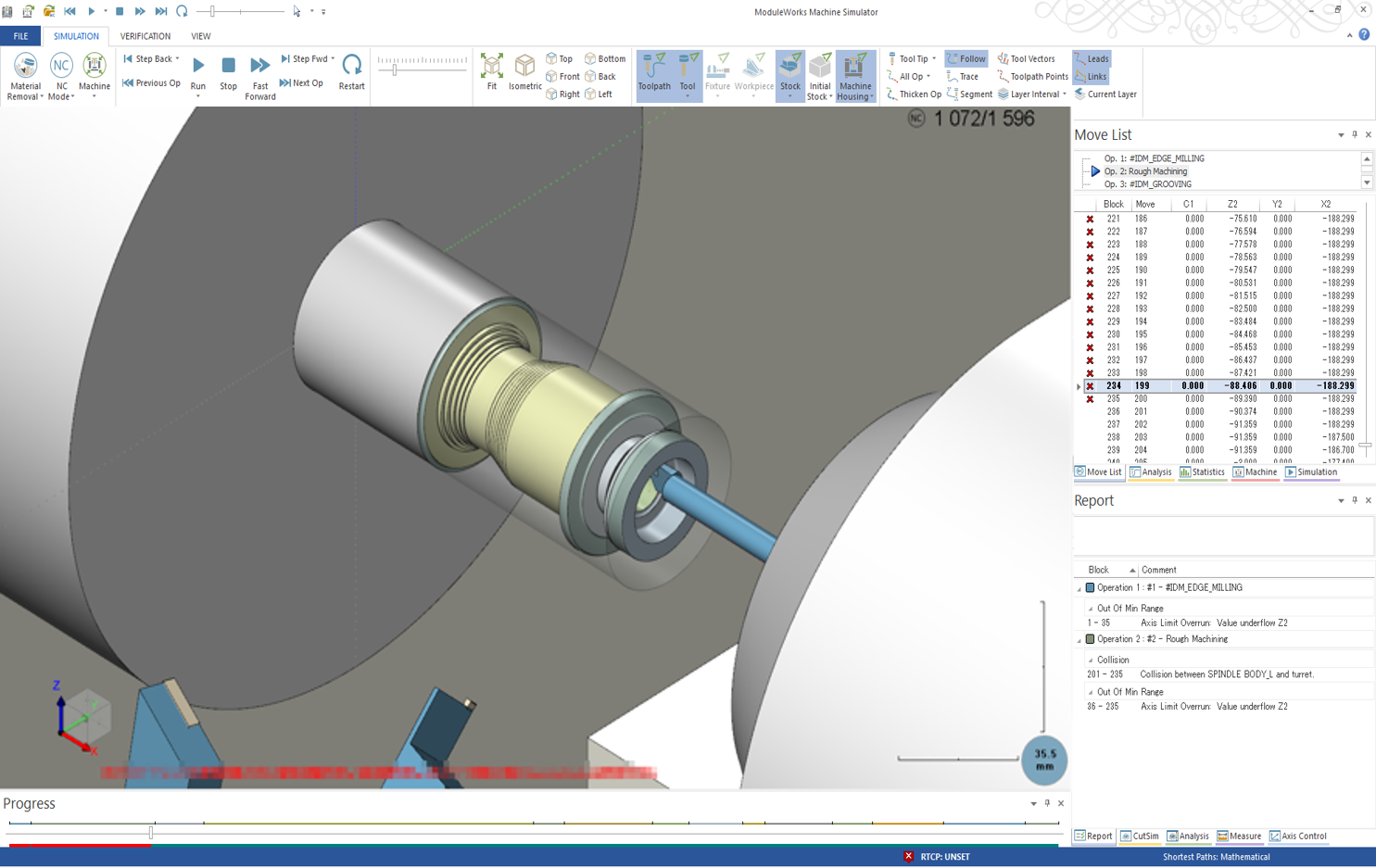
Machine Simulation
A machine simulation function is provided as standard. It enables collision checks between machine structures, tool holders, and workpieces based on CL data, significantly reducing setup verification time.
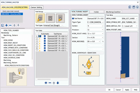
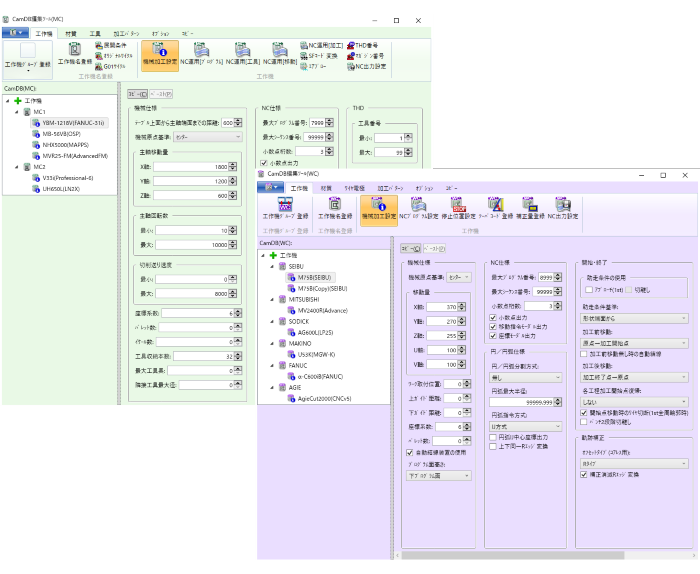
Machine and Machining Pattern Setting
Axis configurations, registered tools, and machining processes for each machine can be defined directly while operating the CAM system, without the need for prior registration.
CAM Function(Common)

Combine Area
If the machining area has a different depth, it joins the same machining depth region. By changing the hole shape created for each part to be drilled by the plate design to the hole shape suitable for machining, the machining efficiency can be increased.
Approach / Edit Approach
Approach setting is available with Helical/Ramping for Machining and with Bell/CR/Slant/Multiple Points for Wire-cutting in addition to Straight Line/Arc.It is possible to edit the different approaches all at once, and make separate settings even for the same defined shape.
Edit Figure
Various CAD drawing functions are available so that you can perform graphic editing process on CAM smoothly to create machining path. Commands such as "Associative", "Stretch", "Corner", etc. are available to edit even the figures with machining attributes while maintaining them as much as possible.
Master
Automation of NC data creation is possible by registering machining pattern, machining condition of tools, material and various machine information. Master edit tools can be operated independently of CAD/CAM application. Edit by referring to the existing master is also possible.
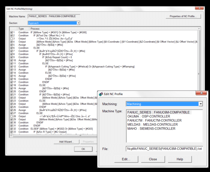
Post Processor
It is equipped with a "post-processor" that supports the machine tools of major manufacturers in Japan and overseas manufacturers, and offers customization and technical support to meet a variety of needs.
OTHER PRODUCT
Product Inquiry
Contact us