SYSTEM MODULE 3D Design
Modeler / Surface Module
Modeling Function
Modeling (Solid & Surface) function allows you to edit figures in consideration of requirements for Molds/Dies. As for surface, uniquely-developed functions superior in peculiar shape processing of dies are available.
Solid Modeling
Solid modeling functions are available such as extrusion, rotation, sweep, loft, cut, fillet, chamfer, draft angle, hole process, etc. Since it is also possible to specify the height on the side of a 2D view, even a beginner can easily perform modeling without any discomfort.
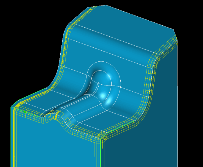
Surface Modeling
Fill/Offset/Trim/extension etc. are available for surface modeling, which is useful for correction after the model import and the handling of complicated free curved surface. *Some surface functions may be optional depending on the system configuration.
Curve
Necessary lines are required on the space to perform 3D modeling. This function supports various curves such as trace curve, reference line, blend curve, fillet curve, etc. to help modeling work. *Some curve functions may be optional depending on the system configuration.
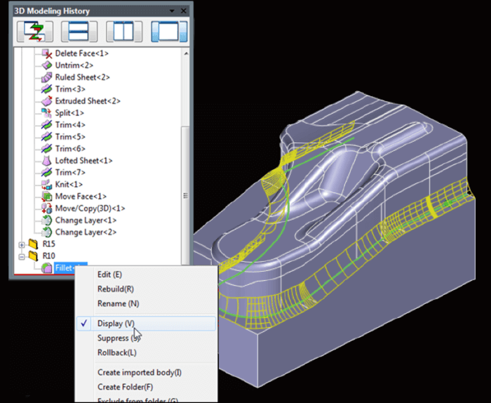
3D Modeling History
Execution history can be recorded for every 3D modeling command. Changing shapes and dimensions, reordering history, and rebuilding makes it easier to update your modeling shapes.. It is also possible to confirm the modeling procedures by rolling back.
Create 3D Plate
2D plate figures can be converted to 3D model by recognition of plate thickness from the figures in side/bottom view or the projection face information, and by reference to the hole information in the drawing. Multiple 3D plates can also be created by batch.
Bending Development
Cylinder bending part can be developed at once. The radius and angle of the bending part are automatically recognized from the product to allows you to develop even if bending surface has formed shape. Lambda values are referenced from the master and it is also customizable.
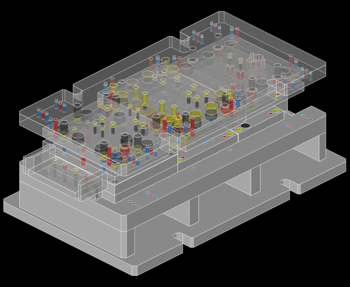
Interference Check
Interference can be checked and removed between the models such as plate and punch created in 3D.
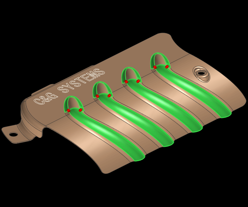
Surface & curve diagnosis
Diagnose curved faces and curves to display the problem points. You can also repair an autorepairable location. You can check the self interference, the break, the spike cut, and the micro edge of the face.
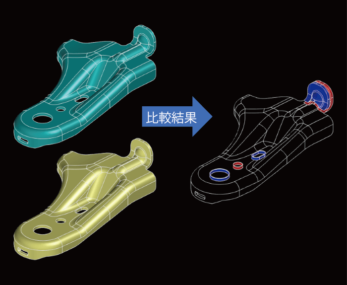
Compare Models
Two bodies can be compared between before and after change by volume and face, and check the change visually. The comparison result can be created as a body to save the result. It is helpful in receiving the data for design change from clients.
CAD Option Module
Mold/Die Extended Function
Support functions for drawing parts as well as for Press Die & Mold design by 3D model are available. It is also possible to customize according to user's own design rules.
Prospective Deformation / Springback / Batch Development / Trim Line Development
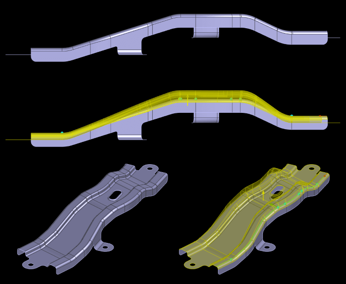
Lift Deformation Prospective Deformation
Moving face surrounded with target deform face on surface body can be moved to the arbitrary direction for creating deformed surface groups. Moving/fixed faces and moving distance can be specified to perform the figure correction easily after trial.
Matching Deformation Prospective Deformation
Deformed surfaces can be created to match points and edges on the surface to arbitrary points and edges. Deformation is possible by specifying deformation range from the fixed surface group or points of before and after deformation to allows you to easily correct the shape after trying.
Rotational Deformation Prospective Deformation
Rotated surface body groups can be created. It is possible to deform by specifying the rotation angle and the reference line. Different rotation angles can be applied to every point. Figure correction becomes easy after trial.
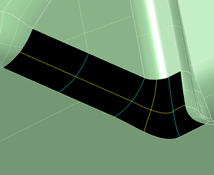
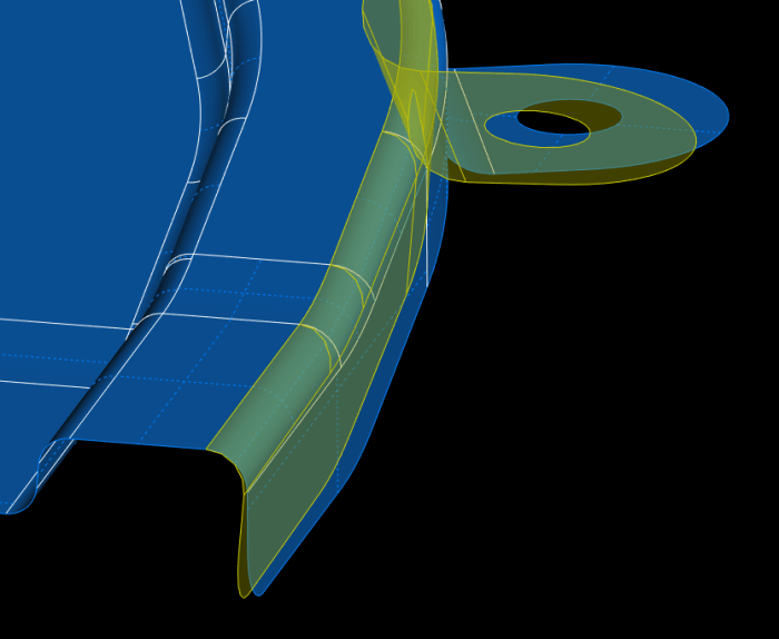
Offset Deformation Prospective Deformation
Deformed adjacent surface groups can be created by offsetting belt-like surface of standing wall, top surface, etc. It is possible to specify the range and offset amount for deformation. Since it is also possible to specify different offset amounts for each point, it is easy to correct shape after trying.
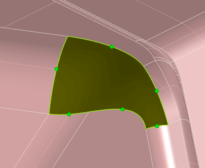
Free form NEW Prospective Deformation
Freeform deformation commands using the FFD method have been added, along with the availability of "Lift Deformation Mode" and "Matching Deformation Mode." The FFD method is capable of suppressing surface distortion even under larger deformations compared to conventional methods. This feature can also be applied to solid bodies.
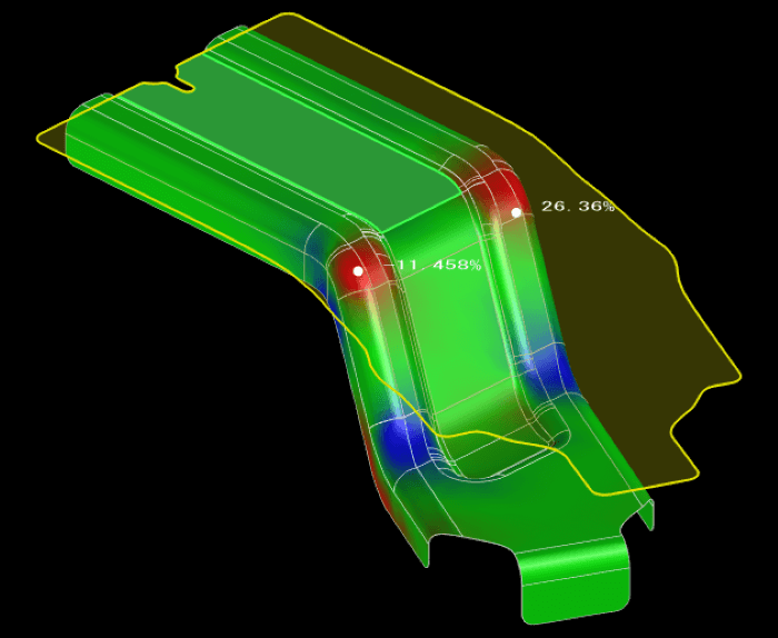
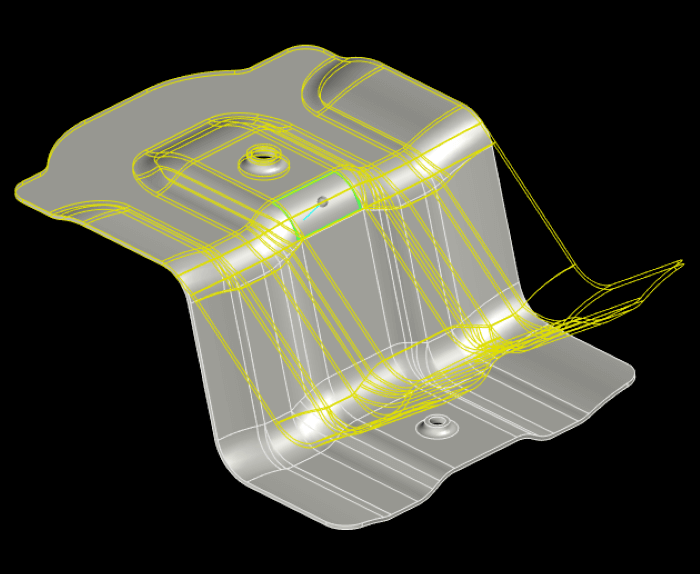
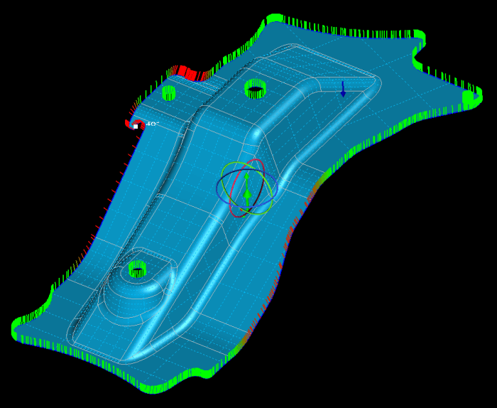
Batch Development Batch Development
Blank shape from 3D model (drawing shape) can be easily obtained with thickness reduction rate as contour display, which helps reduce the trial and estimation process.
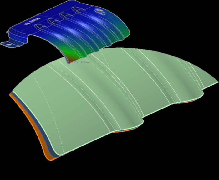
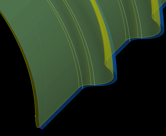
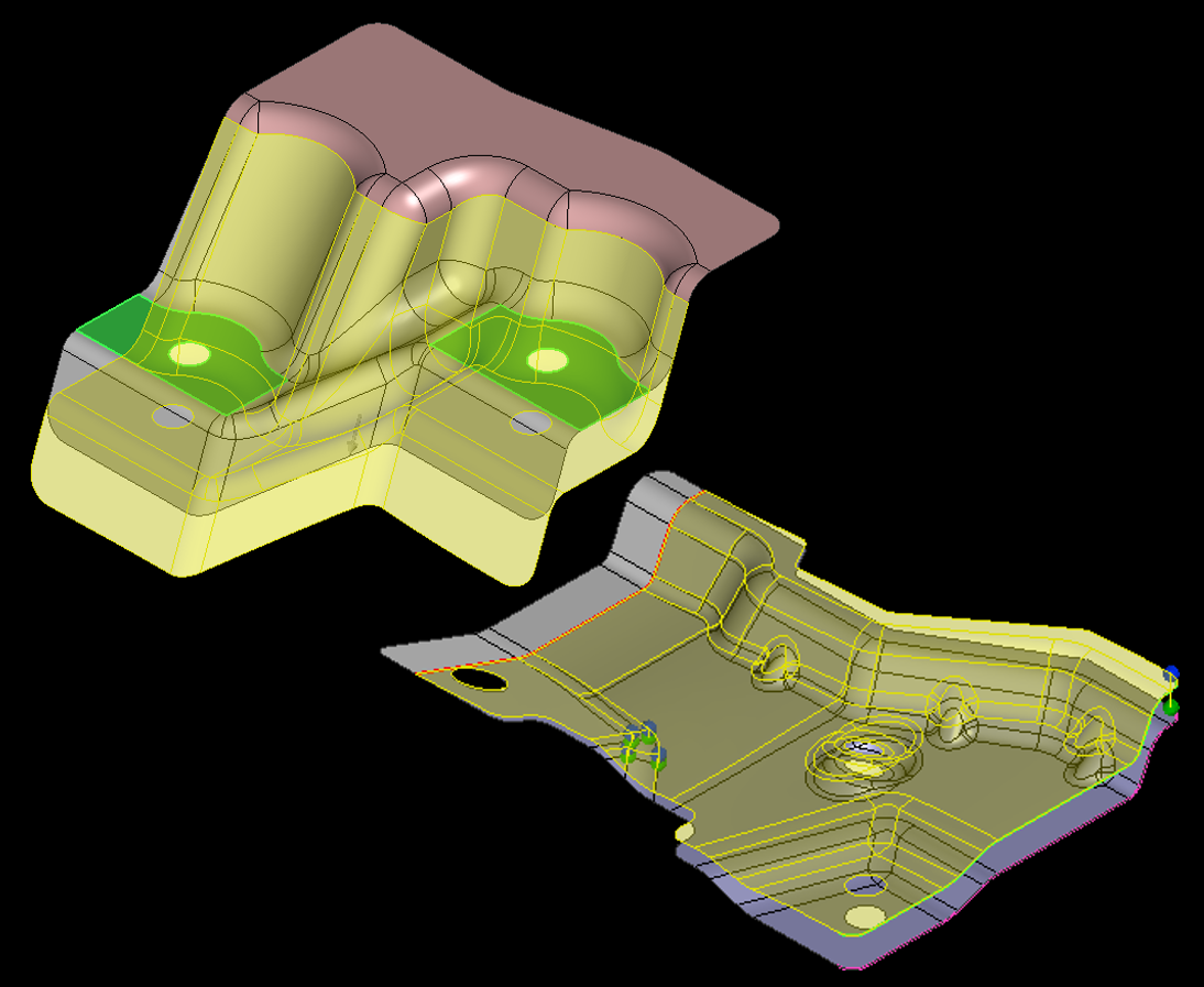
Springback Surface Springback
Springback and prospective surfaces, once experience and modeling skills are required, can be created easily. JSOL analytical solver is adopted as a calculation engine to improve the accuracy of punch-die model creation for the first try, which helps reduce the trial production.
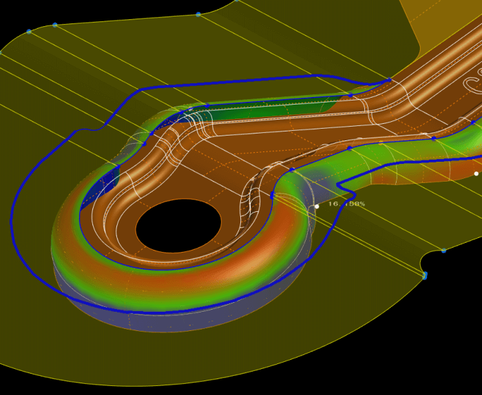
Trim Development Trim Line Development
Developed outline or surface can be created by specifying the surface to be developed in designated direction and angle. Since it is also possible to specify the existing reference shape as a development face, it is easy to create the intermediate shape of drawing product. Contour display such as thickness reduction rate is also available.
Trim conditions Trim Line Development
Trim conditions that are considered when designing the cutting edges of drawn products can be shown. It is represented by normal lines along the trim lines of the development it is facing and is displayed in a color based on the degree between the normal line and the trim reference axis direction.
Press Support
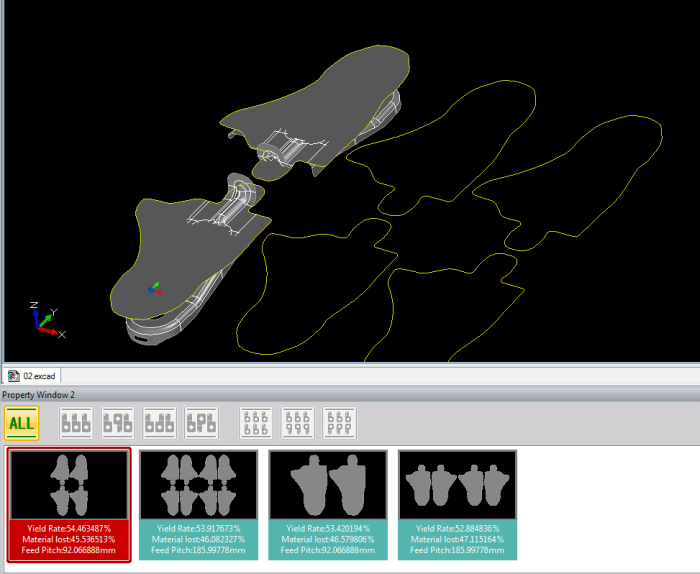
Yield Press Support
Optimum yield can be calculated from 3D blank model based on the conditions such as pitch between products and check angle. Mirror layout and multistage layout are also supported. The possible patterns and yield information can be displayed as well.
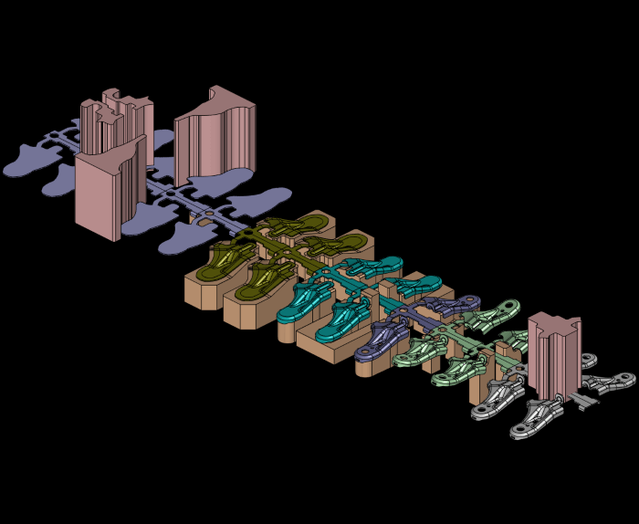
Layout Press Support
Products can be developed into the stages after Yield design. The bending process can be reflected to the model instantly by setting angle, bending, spring back, etc. Press layout design can be performed by the functions such as Create Cutting Edge and Skelton.
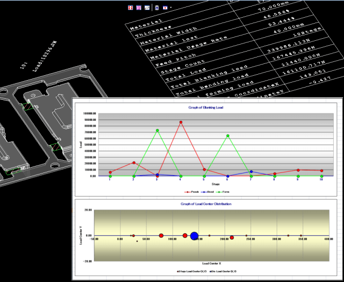
Load Calculation Press Support
Blanking/bending/forming load on every stage and load center of progressive die can be computed. It is also possible to output the result in the drawing document or table.
Mold Support
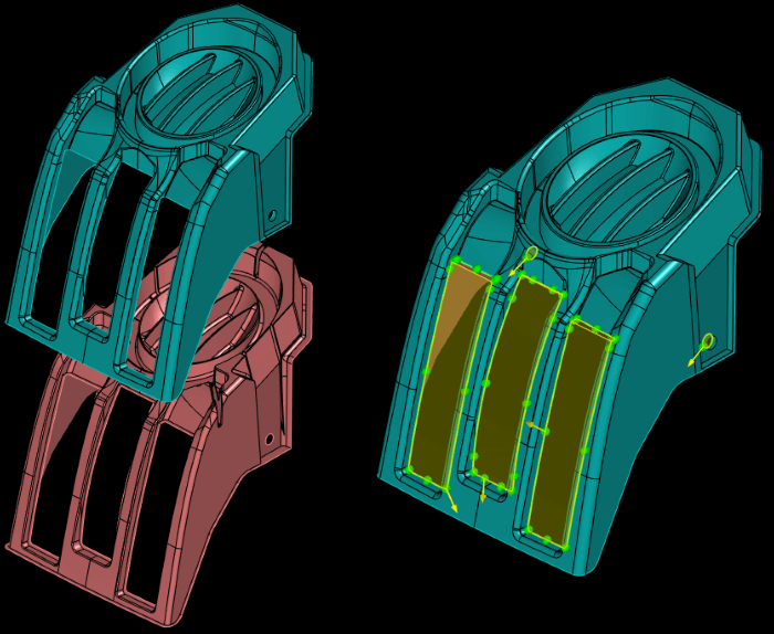
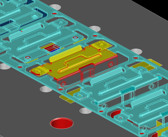
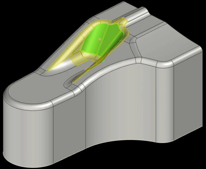
Extract Cavity/Core Surface Mold Support
Split planes can be created (cavity, core, shutoff and parting) semi-automatically. Even when it is necessary to create a splitting plane by modeling, you can use it as a splitting tool just by belonging to a predetermined layer to work without stopping. In addition, since it is recorded as a history, you can modify easily and flexibly even when product design changes.
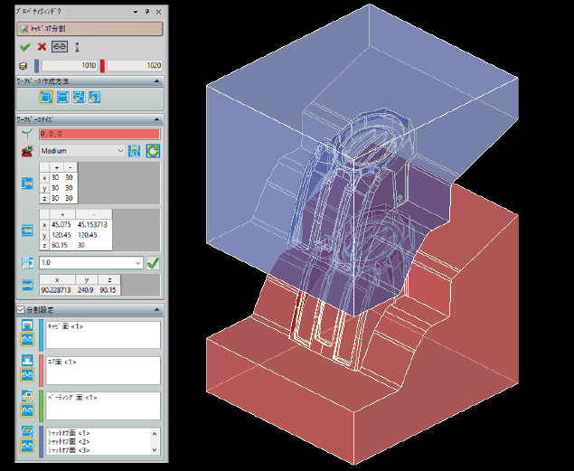
Split Cavity/Core Mold Support
Workpiece can be divided by using the cavity, core, parting, and filling surface to easily create cavity/core. Workpiece size is calculated and rounded from the product shape by specifying the clearance.
OTHER PRODUCT

Product Inquiry
Contact us