SYSTEM MODULE 2D Design
Base Module
Viewer Function
Base module of EXCESS-HYBRID II enables you to confirm information such as draft and thickness analysis, and to create simple dimensions and annotations by taking 2D figure and 3D model.
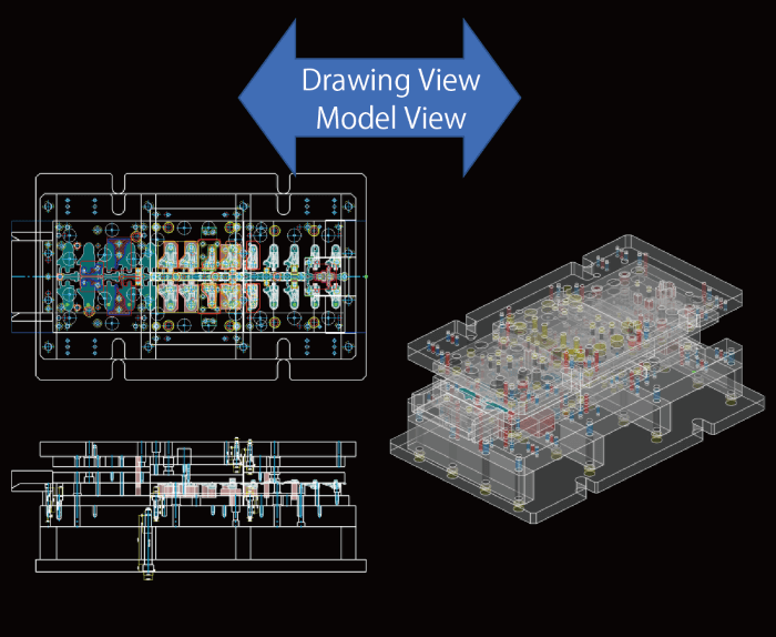
Hybrid Display View
2D figure and 3D model can be displayed in the same document. Hybrid display is available by inserting 3D model into 2D drawings created in the past.
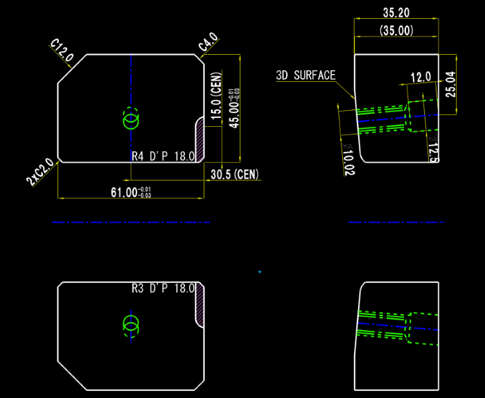
Simple Dimension / Simple Annotation
Dimension can be added efficiently by specifying how to display an arrow or tolerance in the dimension dialog box. Simple dimension can be created such as radius/diameter, length or angle. General annotation and leader annotation are also available.
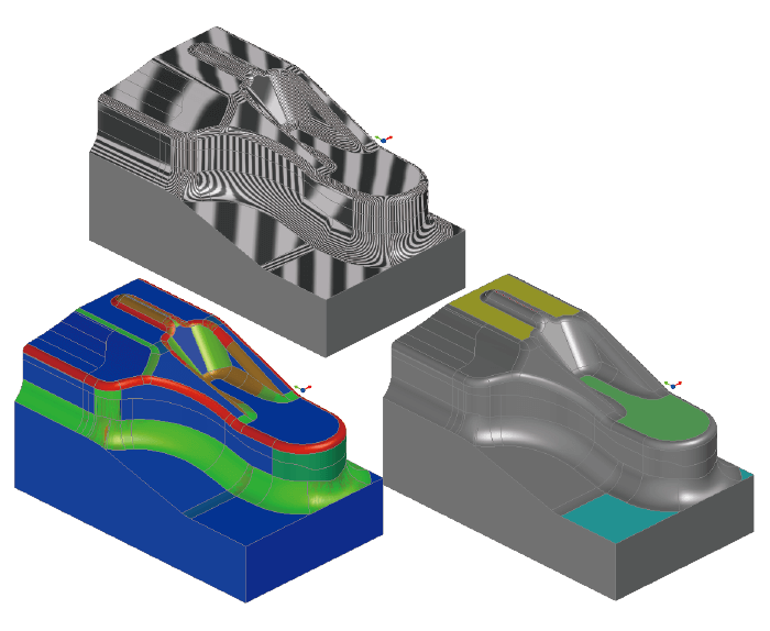
Confirmation function
There are a number of features, such as a zebra display to visually check connectivity between the curved surfaces, a slope and thickness analysis to confirm the formability of the product model, and a flat height checking function in the machining procedure.
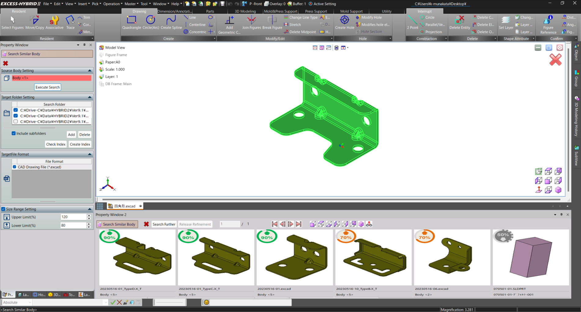
AI Search Similar Bodies NEW
The feature of "AI Search similar body", utilizes deep learning methods to enable AI (artificial intelligence) to analyze data and extract files with high similarity, based on specified models and search criteria. This feature facilitates the rapid identification of highly reusable shapes, providing robust support for designers' thought processes, including estimating expected man-hours and planning processes.
Draw Module
Basic Drawing Function
In addition to basic 2D drawing functions, it is also possible to create 2D section view and 2D drawing from 3D model. Abundant output functions are also available such as batch drawing release, batch file format conversion, etc.
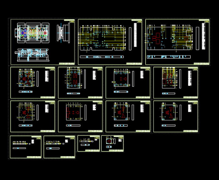
Frame function
You can create multiple parts in a document. You can expand a part created in a drawing into a frame, and you can manage multiple drawings with different scale and paper sizes in a single document.

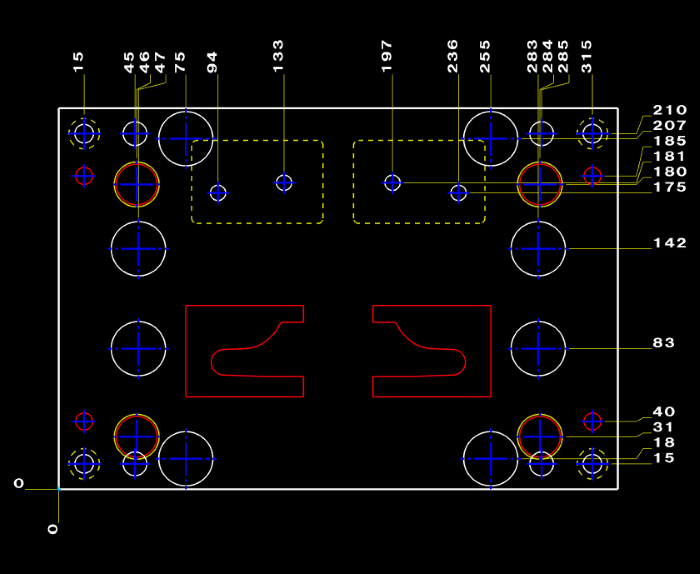
Hole Function / Hole cross section
It is possible to place round/deformed holes with machining attributes, displaying the depth of plate, hole diameter and remaining hole depth. The hole information can be registered as a master. You can also check the interference state, place it in a drawing as a hole list, and output it in CSV format.
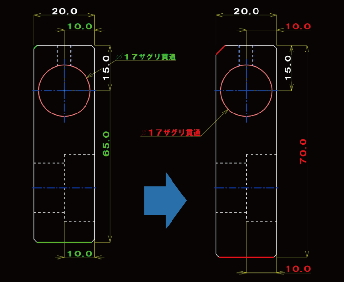
Associative
You can modify shapes, dimensions, notes, and edit them with a single command. Because the specified element type (or part) changes the content, you don't need to select a command for each purpose, so you can significantly reduce the work time of the edited work.
Auto Dimension
Automatically creates dimension for the selected shape. The shape properties allow you to set a scale point to exclude unwanted dimensions. The dimensions you create are grouped, so you can reposition and delete them at any time.
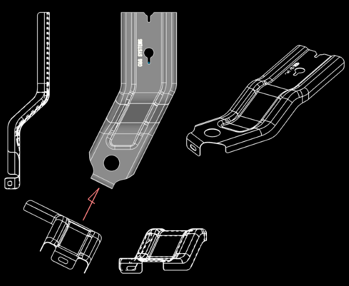
Create Drawing / Section View from 3D Model
Converts an import 3D model (solid or surface) to 2D geometries, such as a front view, a side view, and an isometric view. You can also create a section view and an arrow view.
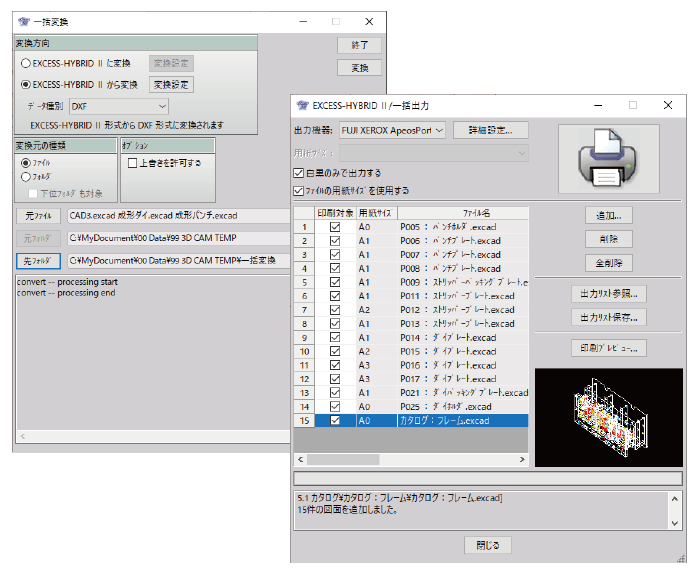
Batch Conversion / Batch Output
Batch Conversion allows you to convert different drawing files into an intermediate format such as DXF at once. You can specify drawing files to be converted in a unit of files or folders. In Batch output, print preview can be viewed and outputted to the printer plotter.
2D Module
Die Generic Function/Parts Function
Abundant command group is prepared to support Press Die & Mold design, which allows you to call standard parts, to create parts list, and to make an auto-release from assembly to parts drawing.
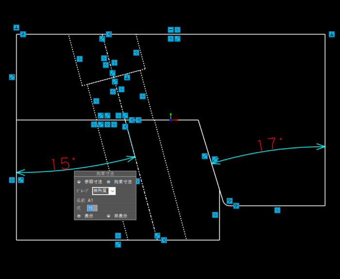
Geometric Constraint / Constraint Dimension
Geometric Constraint and Constraint Dimension can be added to facilitate the shape change. Relational expressions enables parametric deformation linked to the standard dimensions. It is also possible to automatically add geometric constraints such as parallel, vertical, tangent, etc.
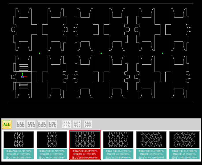
Bend (2D) / Yield / Layout Design
Bend (2D) allows you to create a development of bending figure or process chart automatically for the estimation of blank length. Yield can be optimized based on the condition such as pitch between products and check angle. Layout can be designed with the aid of functions such as Load Calculation and Create Cutting Edge, etc.
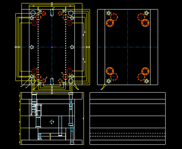
Mold Base
It is also possible to select FUTABA and Nikkata within the Mold Database. You may also arrange its figure with a 3D cavity and core as well.
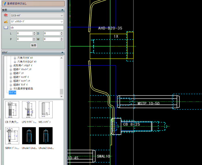
Standard Parts
Standard parts database of FUTABA and MISUMI helps place part figures by simple operation.The layer and part attributes to be placed are pre-customizable and do not require any cumbersome operation during placement. You can easily output a purchase order table by providing a relationship between the part attributes and the hole. You can also register the user's original parts.
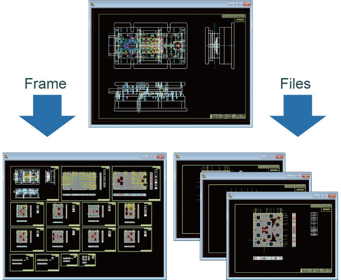
Parts Release
Assembly drawings can be divided into separate part drawings or flame by batch. Part attributes can be described in each drawing automatically according to every user's title block. It is possible to link a drawing and a part diagram between another drawing and another frame, and it is possible to greatly reduce the number of man-hours in the part drawing work.
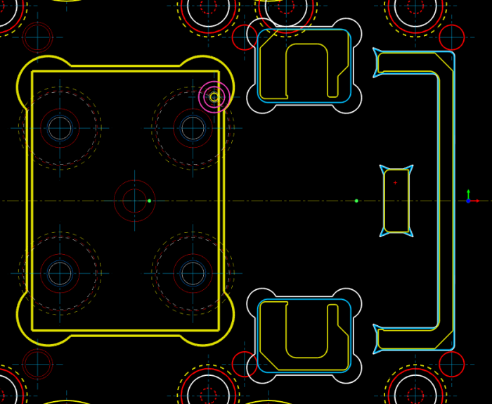
Plate Escape / Auto Clearance
Plate Escape can create an escape figure only by specifying the clearance amount of XY direction and escape type at the corner. Auto Offset can create a clearance figure automatically on the specified layer from the reference figure such as punch. Hole information can be added at the same time in both functions.
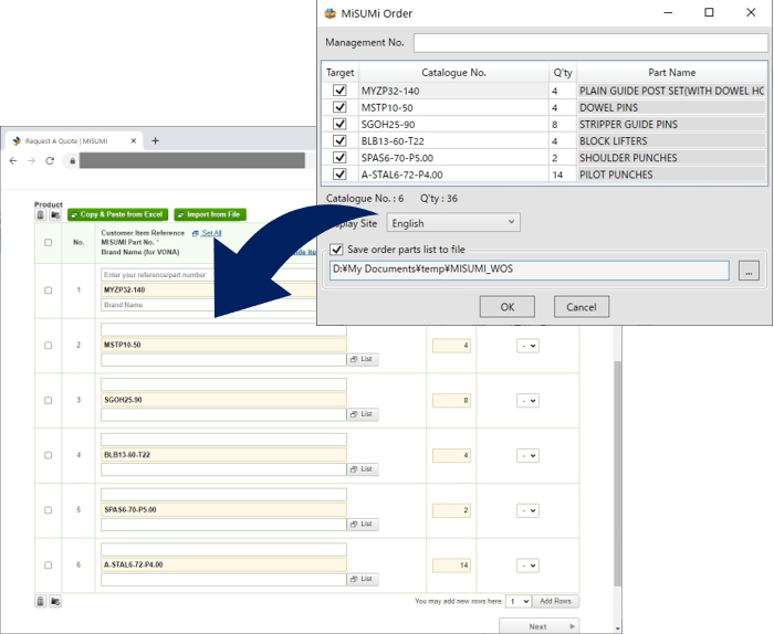
MISUMI Order
One-click enables you to facilitate your order process. Filling the format of [MISUMI-VONA ] will be completed, based on the component part placed in your CAD data.
OTHER PRODUCT

Product Inquiry
Contact us