ADD-IN COMPONENTS
CG Press Design for SOLIDWORKS®
3D CAD System for Press Die

CG Press Design is superior for Layout development, Auto design, and smart association
3D design system for Progressive Press Die. Many specialized functions are available for press die design such as powerful blank/partial drawing development function, layout design function linked with product shape change, die structure design function supporting numerous standard parts.
- FUNCTIONS
- Analysis Option
( Batch Blank/Partial Blank , Batch Drawing development/Spring Back) - NEW Function
- Case Study
Digest Movie
FUNCTIONS
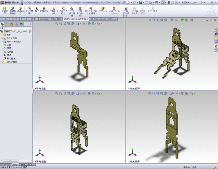
Process body creation Blank Development
Blank body will be created through development of bending plane and die draw. Radius and angle of bending part is recognized automatically, and blank body will be created automatically with K factor from master. Furthermore various development is available such as unnatural bending, burring, spring back, bending restore and so on.
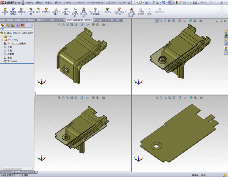
In case drawing shape is included in the same body, batch drawing function is available to develop this part. So you can amend/edit easily because of feature function of history base. We utilize SolidWorks interface, so forming parts also will be developed with ordinary function of SolidWorks.
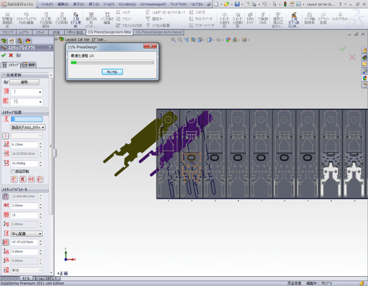
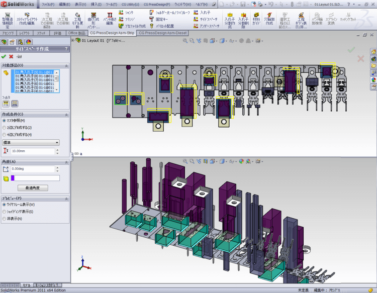
Layout Development Layout Design
Process body will be placed into each stage automatically. Blank layout for nesting, hound's-tooth placement, mirror placement is also available. In addition, layout development for material width, border amount, sending pitch and number of stage are freely considered.
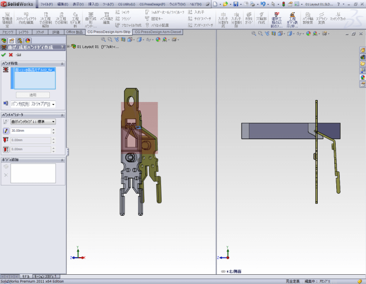
Bending/Forming Punch Layout Design
Bending/forming punch will be created smoothly from cylinder face from bending part and/or forming part. Created bending/forming punch is associated with product, so the designer can check the gaps between product and bending/forming punch, it is easy to confirm and will reduce mistakes during the designing process.
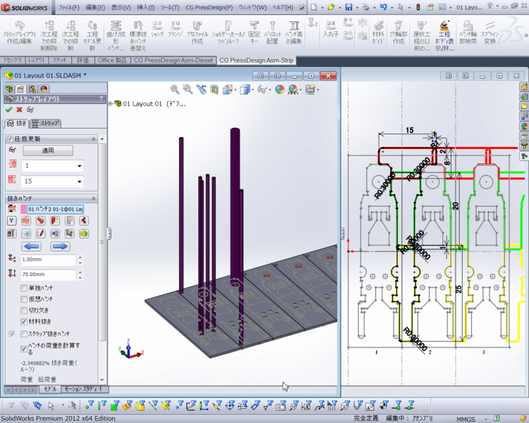
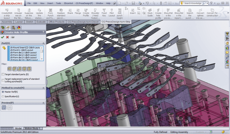
Pierce Punch Layout Design
Pierce punch will be created one time, because sysytem recognize a hole automatically. In case there are lot of pierce hole, this function is effective. And, cutting edge of variant form is drawed by sketch function freely, and profile of products will be traced automatically. And, skecth of cutting edge profile for plural pierce punch is able to create at one time. So, design of punch with matching is available. And/more, we have library for matching, heel, roof, shank, frange.
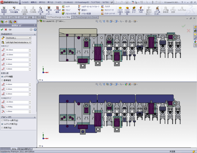
Information of Die Structure Layout Design
In case of designing layout or estimation time, image of die structure appear (including plate thickness, XY size), so created punch dimension will be associated with plate thickness, and position of punch will follow die structure position automatically. So designer easy to consider layout image.
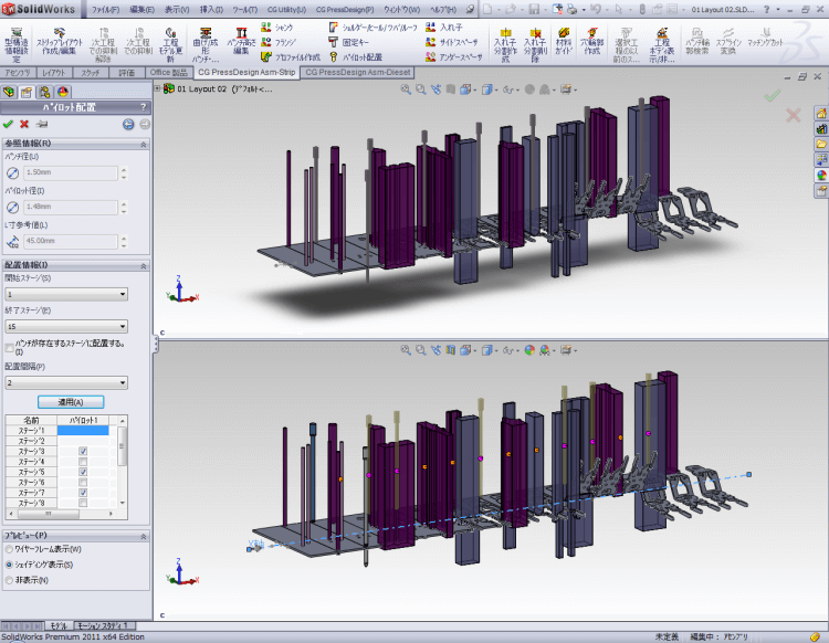
Placement of pilot Layout Design
It is possible to place pilot punch as standart parts. The standard of pilot will be set automatically by setting trimming punch and the information of mold structure and it is possible to change the standard. As placement pattern, it's possible to place several parts simouteniously if you set the condition, such as the range of valid stage, the amount of stage chopping or not place at idling stage. it is also possible that changing the placement stage easily by linking the multi-function of SOLIDWORKS.
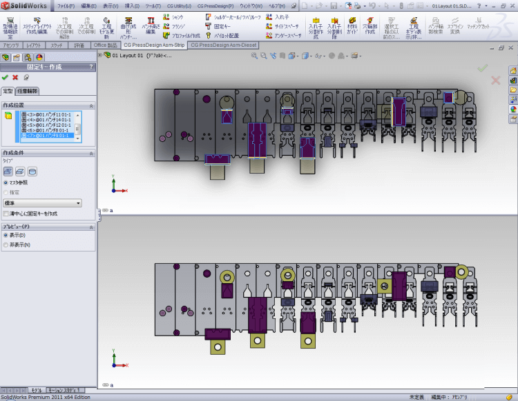
Creation of the anchor key Layout Design
It will create the anchor keys at once by specifying the shank of punch. It is possible to reduce mistake of placement because you can confirm if it interfere with surrounding parts during locating. You can select the key you place from standard parts or product parts. When you placed the key, groove of key will automatically create at the same time. Also, it will support the creation of deformed key which can anchor several punch simultaneously.
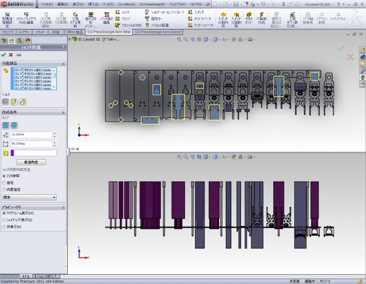
Creation of the shank Layout Design
It is possible to create the master data of shank size that along with the one's rule of standrad. If you utilize this master data, you will be able to create drawing of shank, which is laborious, at once based on choosing the range.
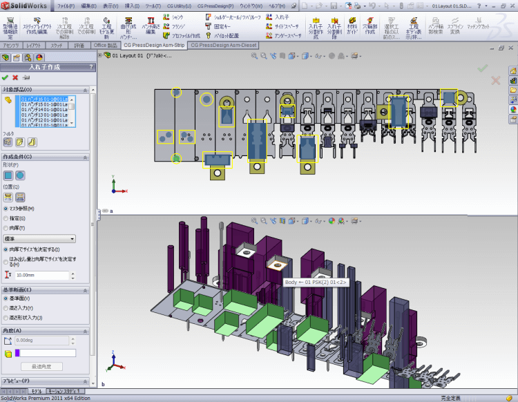
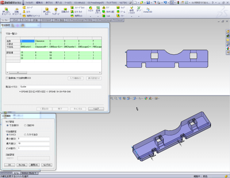
Creation of the insert Layout Design
It is possible to create the master of shank size according to the one's standrad rule. If you utilize this feature, you will be able to create the inserts, such as punch guide, die block at once. You can also set advance setting such as automatical connecting at adjacent the inserts.
Creation of spacer Layout Design
It automatically create underspacer and sidespacer for the insert you created. The underspacer is possible to set several spacer according to the one's rule of polishing parts and sidespacer is also possible to insert according to the direction of placement position.
Creation of the guide Layout Design
It create mold guide easily in the mold. Position of the guide is determined by automatic recognition of the work. It is also possible to do treatment of clearance for pilot and lifter at the same time.

Unit Die Structure
Internal standard parts such as springs and suspension bolts, inserts and bolts will be registered as standard unit parts. Adding coincidence, dimensional binding, relational formula between parts, each part size, each part place will be up-dated automatically. So design standardization and a reduction in design time will be possible.
Customized parts Die Structure
Ordinary internal parts will be registered as customized parts, so you can create your own catalogue. Registration work is an intuitive and easy operation.
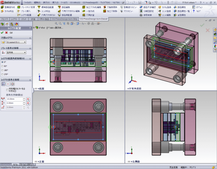
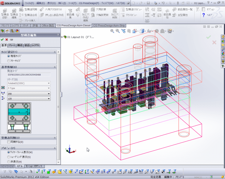
Die Set Die Structure
CG PressDesign supports standard die set from FUTABA. It is easy to change plate size, and easy to insert new plate etc., so customized die set is available. Frequently used parts such as clamping bolt, knock-out pin, stripper bolt, register to customized die set, so it reduces design time for the die set.
Standard Parts Die Structure
There are 6,200 libraries for Futaba and Misumi standard parts. Sandard parts image appear in the screen, so easy to set for value of position and length on the plate. And template of machining is standard feature, so easy to set attribute of hole. And L dimension is associative with plate thickness, so length of pin will be optimized automatically.
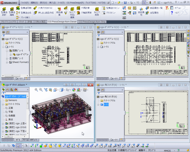
Parts Release Drawing Supports
2D drawing will be created automatically from assembly file and parts file. And parts list, purchasing sheet, title block will be created same time. Hole list, auto dimension will appear on the title block after parts release.
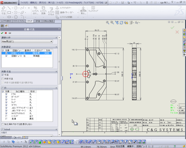
Auto Dimension Drawing Supports
Dimension will be created automatically on the drawing. Dimension type is able to select each projection and hole attribution base is available. Dimension pattern will be registerd in to the master, so dimension will be created separately each plate such as punch plate, die plate.
OTHER PRODUCT

Product Inquiry
Contact us

© Copyright 2010- C&G SYSTEMS INC. All Rights Reserved.