SYSTEM INTERFACE
SYSTEM INTERFACE
Intuitive operation environment that does not interrupt thinking
HYBRID VIEW
Unique Hybrid Technologies
Drawing concepts not found in conventional CAD are incorporated. Adding 3D information to each 2D part drawing enables three-dimensionalization from the drawing, 2D designing while displaying 3D model in the drawing, and insertion of 3D model in the drawing etc. We provide hybrid design environment with unique technology combining drawing and modeling, which makes it easy for the operator to visually confirm and judge, and allows intuitive operation without interruption of thought.
About HYBRID VIEW(Japanese Video)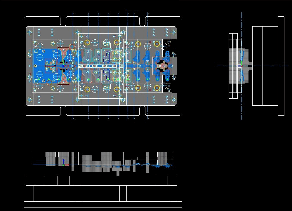
Drawing View
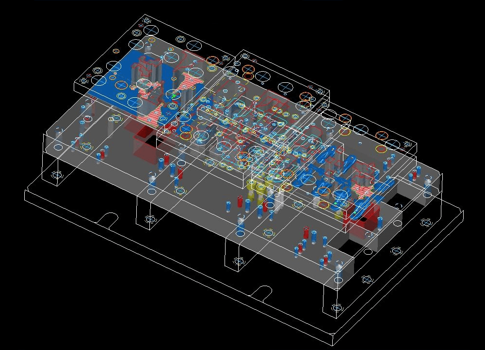
Model View
USER INTERFACE
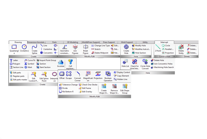
Ribbon Menu
Ribbon menu similar to Microsoft® Office is newly supported. Working efficiency can be improved by customizing it to display frequently-used commands in each working area.
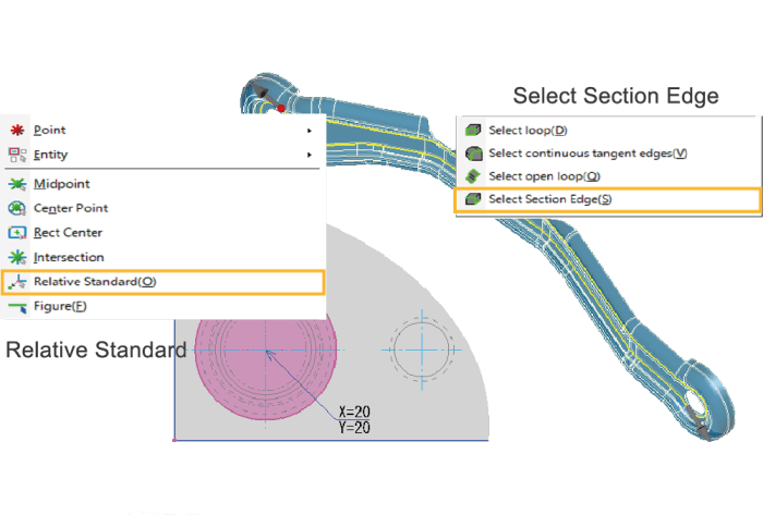
Input Assist
Makes time-consuming input operations more efficient. For example, you can easily input coordinates relative to a target point without using construction lines, and quickly select the group of edges needed for modeling by selecting cross-sectional edges.
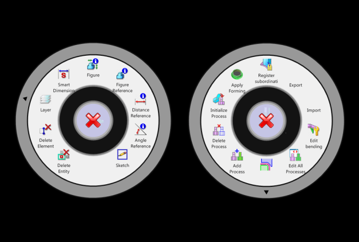
Preceding Selection
Menu selection is possible after selecting an element. It is possible to create drawings intuitively.
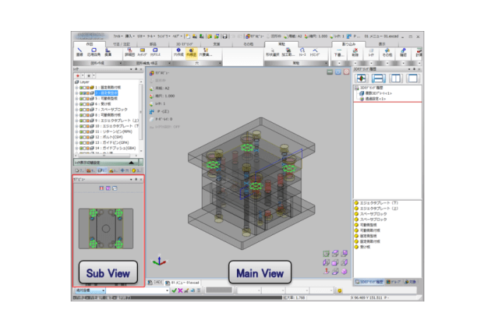
Sub-view
Sub-view, which can provide simultaneous display and operation of Drawing View and Model View, is now supported. During modeling, it is now possible to improve operability and visibility, such as by selecting Outline Figure = Drawing View, by specifying that Height = Model View, etc.
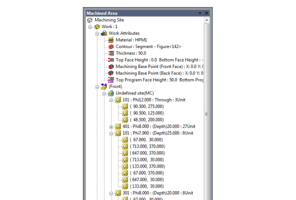
Machining Area Tree(CAM)
Workpiece, Machine tool, Front/Back, Part information, etc. are displayed in detail by tree structure. It is possible to change and confirm the machining order, as well as processed, suppressed, defined and deleted for each node. Process to create NC data can be simplified.
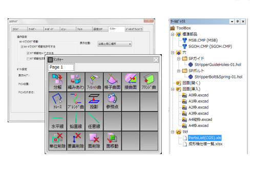
Launcher / ToolBox
Operating environment with excellent usability is freely customizable. It is more operable to register frequently-used commands at Command Launcher, and more efficient to call for information instantly once you register such as frequently-used drawings, EXCEL list, or parts/hole data in Tool Box.
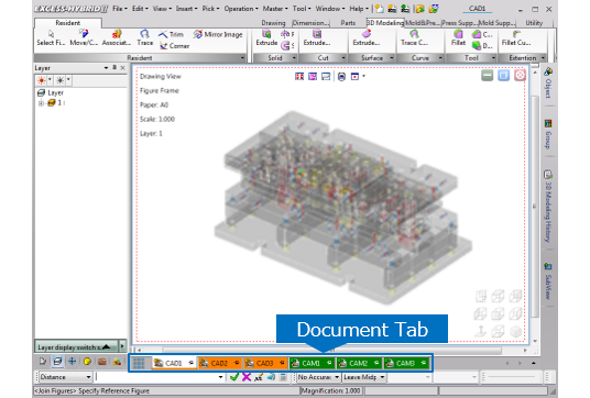
Document Tab
Documents can sorted by drag & drop operation. It’s also possible to fix windows that are displayed preferentially by pinning, and you can work with the edit drawing and the reference drawing separately. In addition, the background color of the tab can be set for each CAD/CAM, which improves the visibility.
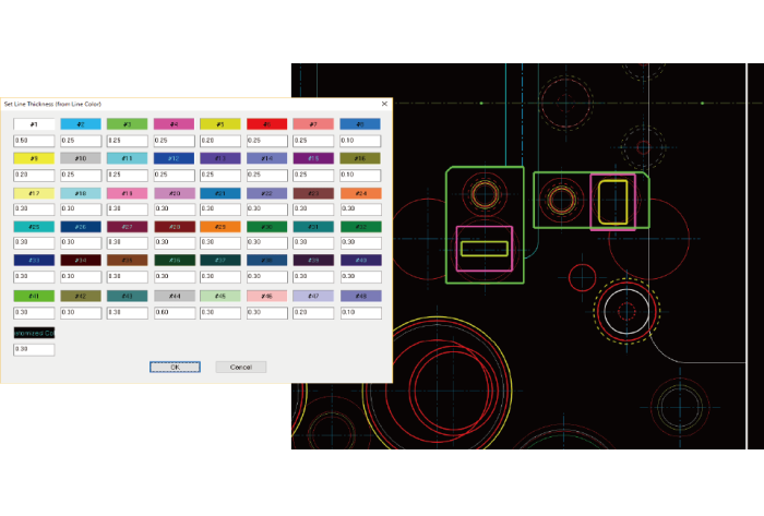
Line Width Display
Line width of 2D figures and edge width of 3D models can be set to display on the screen. For 2D figures, the line width for printing is automatically set from the line color and width of the figures. For 3D models, you can set the width by the edge type, such as wire, surface, solid, etc. Visibility of drawings and models improves by setting according to intended use.
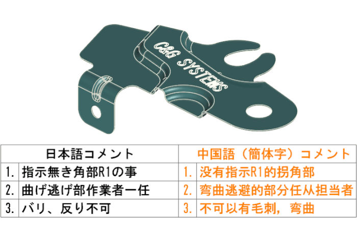
UNICODE Support
"UNICODE" which can handle major languages. This ensures compatibility of drawing annotations in Asian countries and regions including English-speaking countries.
Data Translation
Abundant conversion parameters reduce man-hours after the conversion by supporting standard and major CAD formats. In addition, CATIA-V5 data can be imported with an option.
Seamless data coordination between CGS products is realized. It is possible to transfer model data or machining hole attributes data.
* CATIA is a registered trademark of Dassault Systemes
* SOLIDWORKS is a registered trademark of Dassault Systemes SolidWorks
* Parasolid is a registered trademark of SIEMENS Corporation.
Customize
Customization is available according to user's design environments.
- Standard post processing / machining path
- Special process of drilling/wire cut
- Application (automation, simplification) for die designs
- Exclusive drawings (exclusive parts list, exclusive die structure design etc.)
- Press cutting edge creation / development
OTHER PRODUCT

Product Inquiry
Contact us