ADD-IN COMPONENTS
CG CAM-TOOL for SOLIDWORKS®
CAM System for Molds & Parts

High-precision CAM system with totally simplified operating environment, utilizing the reliable "CAM calculation program".
For 3D CAM, the reputable CAM-TOOL's CAM strategies for polygon and surface shapes are adopted.
High-precision and high-efficient machining can be provided, as users operate the system to match the required products quality.
Furthermore, from the processing attribute of the model designed by "CG Press Design / CG Mold Design", we can maintain consistency among product series, such as automatic process creation.
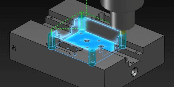
USER INTERFACE
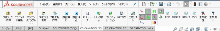
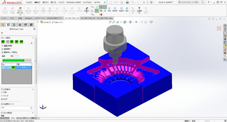
Main Menu
The user-friendly interface enables the user to create NC data easily, using the main menu in order from the left. To create NC data, users only need to prepare a machining project and apply a template, then start CAM calculation and check the results.
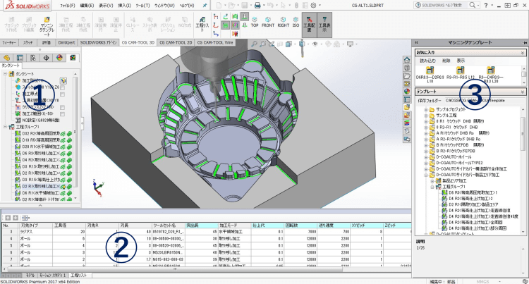
Project Setting ①
All parameters related with machine settings, such as "Project type" (3-axis or Multi-axis), "Shape to machine","Stock", "Cutting origin" and "Tool initial position", can be specified on the single dialog box. ①
Process List ②
"Process List", corresponding to the project tree view, assists in the safe and accurate operation. Some parameter values can be confirmed and revised on “Process List” too.
Template ③
Template is the function to save and recall standardized processes. Users can apply reliable machining processes easily after machining projects or processes are registered as "Favorites".
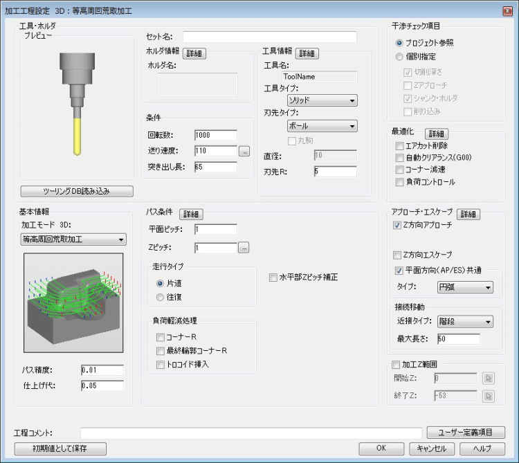
Machining Process
Main dialog box consists of only main parameters. Others are allocated on detail dialog box. Specifying a formula by using "Macro variables" as a parameter value is also available. This allows the revision of some input values automatically, such as lead-in radius relating with tool diameter, when tool-diameter or feed-rate, etc. are changed.
CAM Function
Optimization / Cutting Simulation
In addition to the Optimization system like CAM-TOOL's, there is a Simulation process that uses the Tool and Holder data from the Tooling DB to verify safe results. “Delete air-cut”, “Auto clearance” and etc. help users to create more efficient and safer tool-paths too.
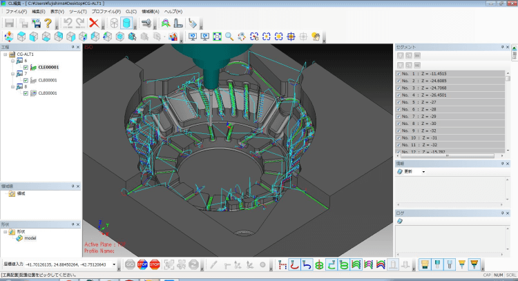
CL Editor
CAM-TOOL's reputable CL editor is adopted into the system, which provides the verification and edit functions of tool-paths, such as "CL Display", "CL Information", "Move/Copy", "Delete", "Change Approach Position", "Change F Value" and etc.
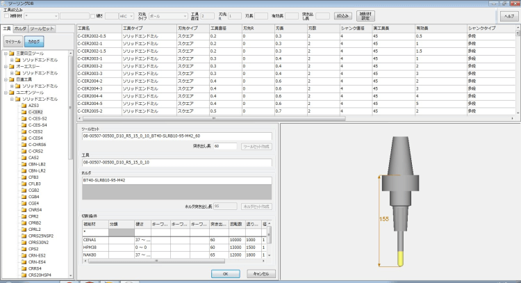
Tooling DB
"Tooling DB" manages cutting-tools, holders and machining conditions. Users can define the shank with multistage taper or R-shape, and this makes an interference check more precise. Cutting-tools and holders can be prepared easily by downloading catalog data of tool/holder manufactures from WEB site.
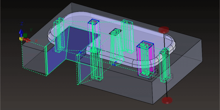
3D CAM
Z-level Roughing
Create Z-level offset tool-paths for roughing. "Insert trochoid" and "Insert R" reduce the cutting-load, and contribute to keeping a constant feed-rate. Non-rectangular solid can be specified as "Stock", which allows users to create flexible tool-paths corresponding to machining conditions.
Z-level Scan-line Roughing
Roughing mode by Z-level & Bidirectional cutting.This cutting mode brings benefits to roughing for large stock with long distance tool-paths, and enables to reduce machining time because of less deceleration. Supporting both of core & cavity shapes, the system automatically recognizes the cutting areas and generates tool-paths, even if the shapes are complex.
Rest Machining
The system automatically detects the uncut area of previous process, and generates tool-paths for the remains. It is possible to machine efficiently for each portion, cutting by along-surface tool-paths at gently sloping area, and cutting by Z-level tool-paths at steep and groove area. The uncut area can be recognized correctly since any types of cutting-tool (ball/radius/square end-mill) can be utilized.
Z-level Finishing
“Z-level Finishing”, which performs climb milling, assures quality high speed and high-precision machining. Spiral tool-paths can be also created, which contributes to the reduction of connecting-moves. This is the best way to machine automatically since gently sloping area and horizontal area can be also executed at once.
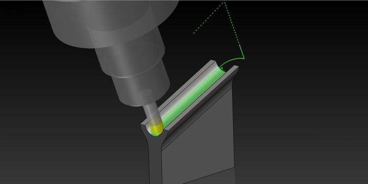
Corner Processing
Creating tool-paths for concave ridge-line portion where smaller cutting tool is often used. It is possible to reduce the cutting-load because the system controls cutting direction automatically corresponding to the angle of the ridge-line. Moreover, "Driving-in", which removes the stock step by step, contributes to maintain
Low Angle Finishing
The system extracts gently sloping portion automatically by specified angle, and generates tool-paths there. Users can select "Scanning” or "Offset Path" (around the area) as a traveling type, so that it is possible to machine efficiently corresponding to the feature of "Shape to machine".
Surface Finishing
Creating tool-paths along the mesh direction of the specified surface. This cutting mode is useful for additional-machining and part-machining, and also considers the safety of processing for the gap between surfaces.
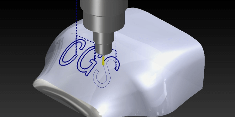
Curve Cutting
This cutting mode corresponds to the engraving for "Sketch" or "3D Sketch" entities. It is possible to machine groove-portion, edge-line and letters-on-surface precisely, utilizing "Drive Z" function.
Pencil Cutting
Not only ball end-mill but also radius and square end-mill can be used for pencil cutting. Tool-paths are created along the edge-line which the system automatically detects.
Horizontal Area Cutting
The system automatically extracts horizontal area from “Shape to machine”, and generates tool-paths there. Tool-paths are supposed to travel around the area with climbing-cut direction. This cutting mode is useful to machine horizontal area with radius or square end-mill.
Face not to machine / Different stock surfaces
"Surfaces avoiding to machine" or "Surfaces with different stock from others" can be specified at "Shape setting". It allows more efficient tool path for machining to be created easily.
Divide CL
The function that divides CL by [Cutting length] or [Machining Time] . CL can be divided considering tool life, and operation time for creating processes also can be reduced drastically.
2D / HOLE
2D / HOLE
Hole and 2D machining are integrated to 3D machining project. 2D and Hole entity, Template, Cutting DB drives CAM automation.
[ HOLE ]
It is possible to create drilling data on not only a plate but also 3D surfaces.
[ 2.5D ]
It is possible to create 2.5D machining data, by recognizing "Sketch" entities or "3D model data".
WIRE
WIRE
Intended wire cutting can be achieved by the flexible cutting patterns and various lead-in types, recognizing target WC-contours easily.
3+2 AXIS
3+2 AXIS
High-precision 3+2 axis machining data of HOLE/2.5D/3D millings can be created, defining the machining direction for each process. "Delete air-cut" for multi-axis machining is also available in "Optimization".
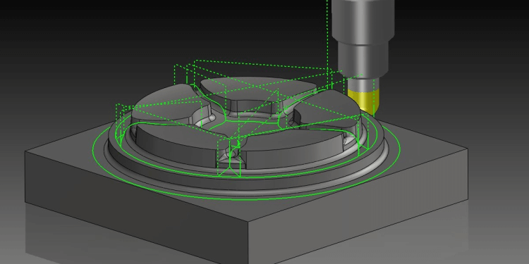
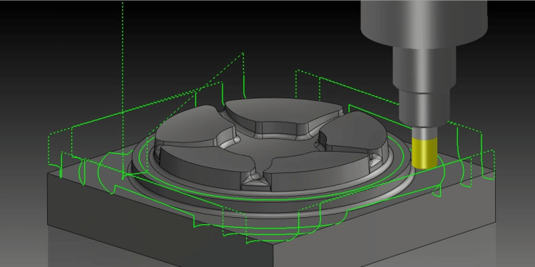
Milling Sample
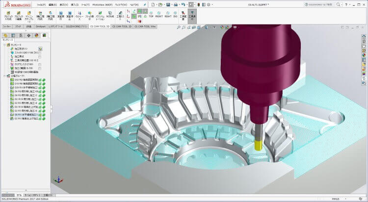
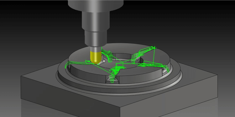
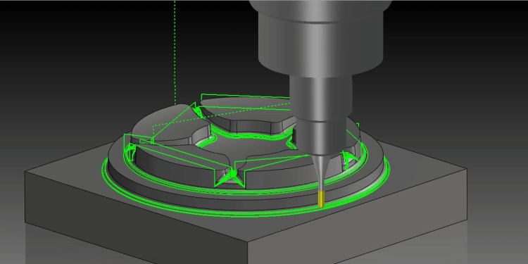
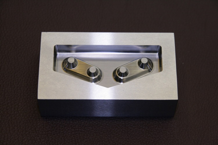
Hub cavity(Miniature)
Hub cavity has 4 core cone at gradient surface. Since there are remaining area which the roughing tool can't cut into, remaining volume can
be unequal. Furthermore, it has turned edges which the tool load becomes large.
-
《 Point 》
- Rest machining with low tool load variation.
- Smooth movement to keep off cutter mark by instantaneous dwell at turned edge.
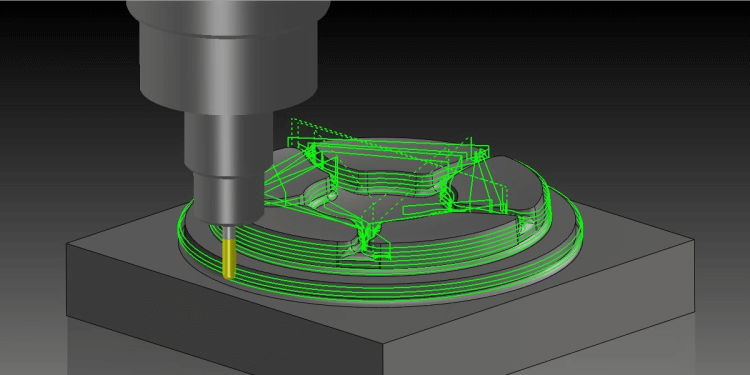
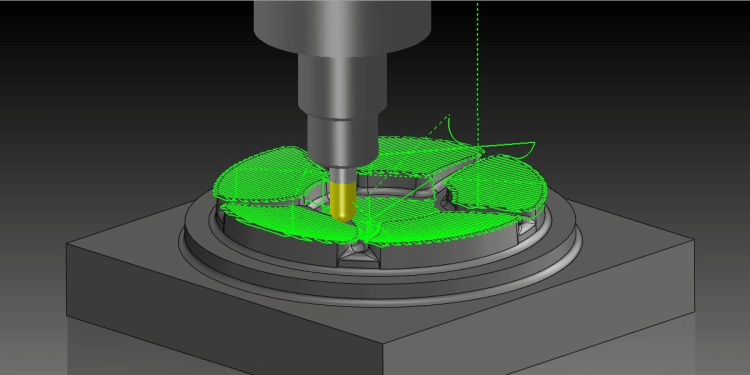
Brake lamp(Miniature)
Brake lamp has machined with Z-level Roughing, Rest Machining, Z-level Finishing, Scanning, and Corner Processing.
《 Z-level + Low Angle Finishing 》
Since the second step is not a horizontal plane but tilted plane, it was machined by Z-level Finishing with constant cusp height. The bottom flat area was machined by Low Angle Finishing. With this combination, it was machined with few approaches and escape even if the gradient changes dramatically.
NAK80(38HRC Equivalent)100mm x 60mm x 30mm
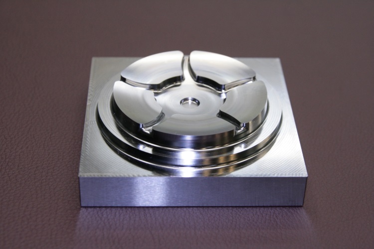
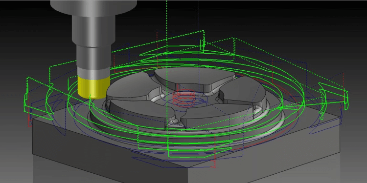
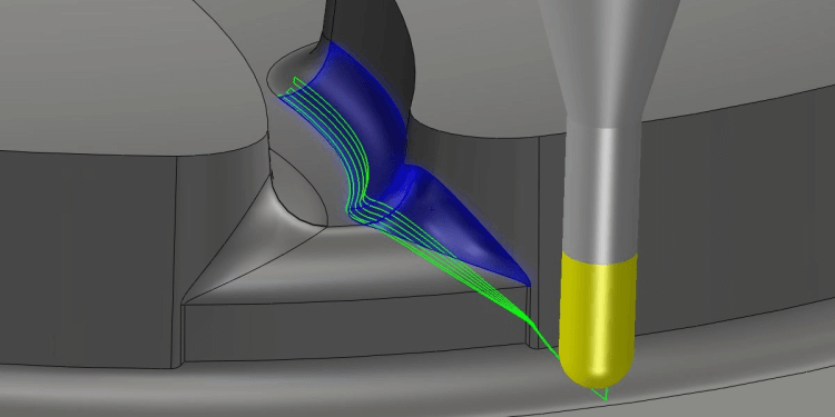
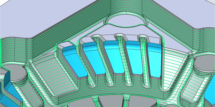
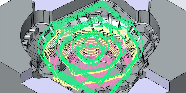
Wheel(Miniature)
Set the range of machining and separete machining area then machining for finishing. From center to five grooves, its side and bottom are machined by spiral cutting in Z-level finishing and be seamless at each area. More over, it succeeded in restraining occurrence of the step difference. It uses the mode of part machining and the whole work is machined as circumduction. It is possible to achive such advancement machining by using the range of machining.
DAC(the equivalent of 49HRC)100mm x 100mm x 30mm
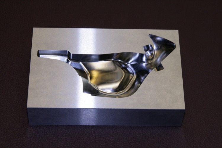
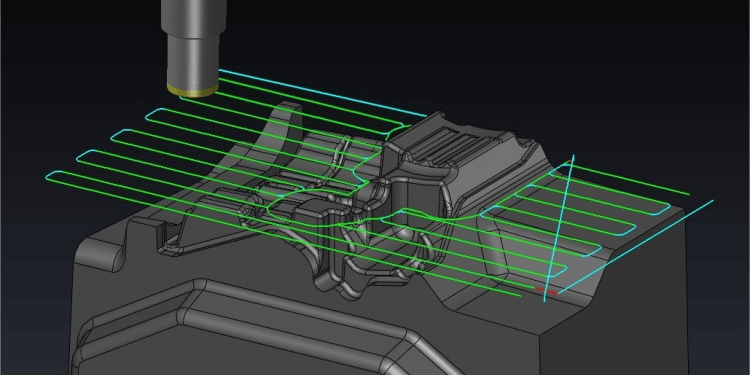
Bike/Sidecover (Miniature)
This model is composed by several free-form curved surfaces, and we created the process that tool changes its size from radius 3 to 0.5 to machine deeply. In the process of rough cutting, it machined gentle area after rough cutting by tool radius 3, and output tool-pass for area of leftovers where will be machined by tool radius 2 as re-machining. Finishing whole model is combined Z-level line with scanning line at Z-level finishing. They overlap each other at area when an incline is changing continuously.
STAVAX(the equivalent of 52HRC)140mm x 90mm x 30mm
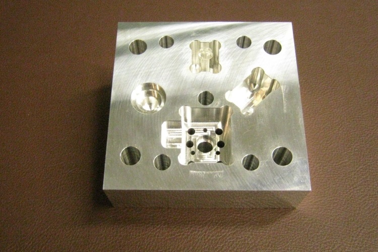
Hole/Pocket
HOLE:
It machined holes, such as guide post, the hole of return pin, which exist on plate of press and mold. On the others we machined with this is tap hole, drill thru hole, the hole for bolt, 2 step-drill hole, clearance hole for pockets of 4 corners, and also 3 step-drill hole and the inclined pocket which has 15 degrees.
2.5D:
What we machined is the pocket which has step, the pocket which is inclined 10 degrees on its plate and the pocket on whole model which is inclined 15 degrees.
Aluminum(the equivalent of A7075)120mm x 120mm x 40mm
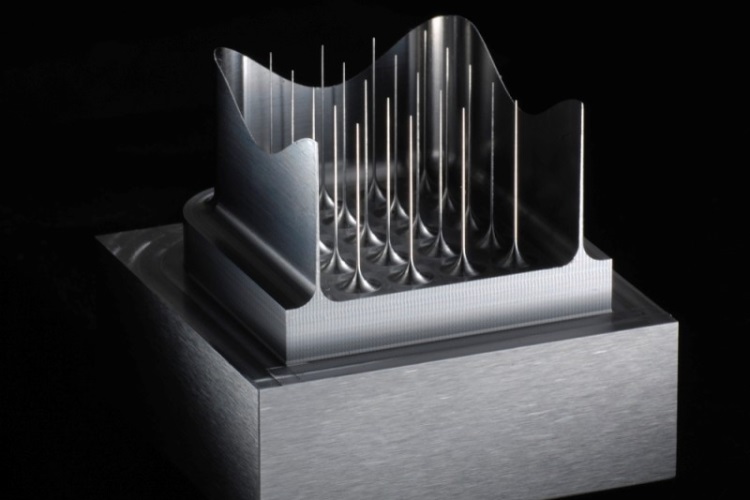
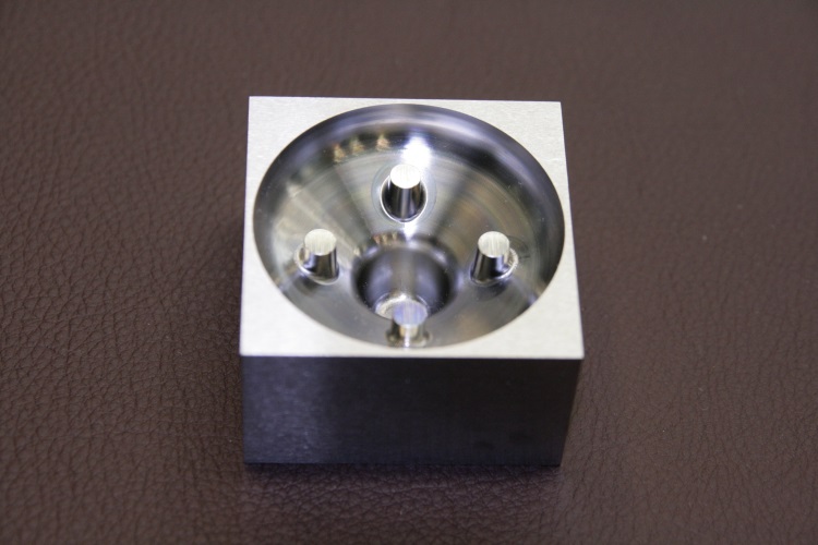
Pin holder
This is a sample that machined fine tiny pin and thin wall. Specify plane pitch 2 times and doing rough cutting and finishing by sololy process. High accuracy and uniform tool pass and reducing the stress of finishing by setting the final plane pitch, to be realized machining tiny fine pin. The diameter for top of pin is just 0.12 which is very tiny and fine and is required high roundness. CG CAM-TOOL is possible to machine such a high accuracy becouse it can calculate tool pass which is tiny, fine and uniform.
NAK80(the equivalent of HRC42)40mm x 40mm x 35mm
OTHER PRODUCT
Product Inquiry
Contact us

© Copyright 2010- C&G SYSTEMS INC. All Rights Reserved.