ADD-IN COMPONENTS
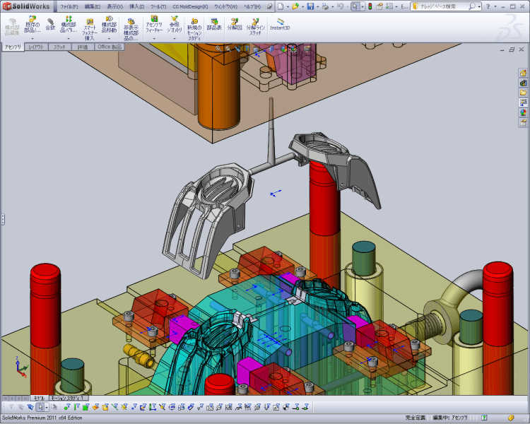
CG Mold Design for SOLIDWORKS®
3D CAD System for Injection Mold

This is a perfect tool that totally supports processes from mold design to drawing creation.
3D design system for Mold at middle and small size parts. Numerous functions specialized in mold design are available, such as shrinkage function, cavicore division function, slide design function, ejector pin creation function, electrode creation function, die Structure design function supporting numerous standard parts.
Digest Movie for SOLIDWORKS2013
FUNCTIONS
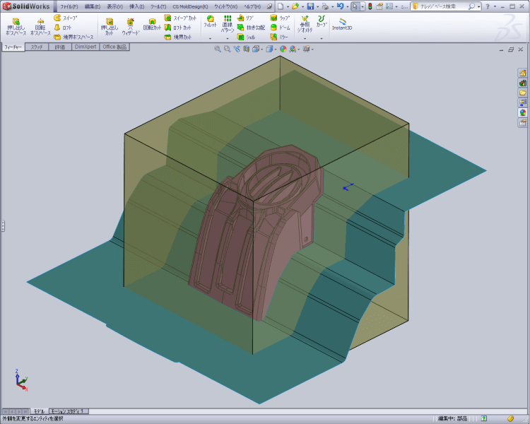
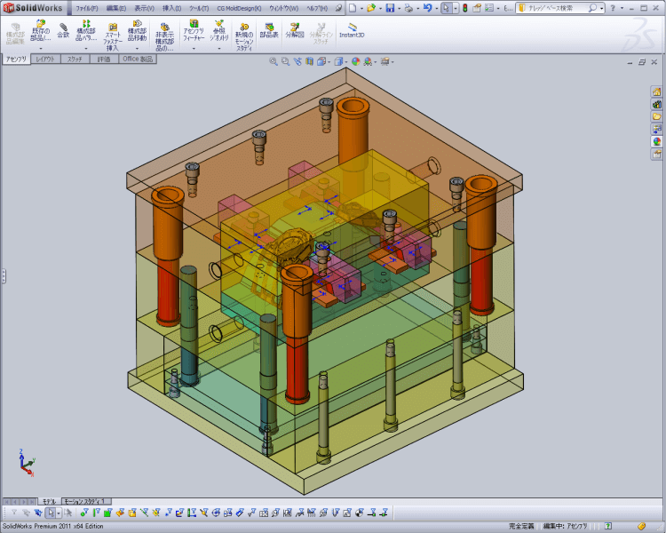
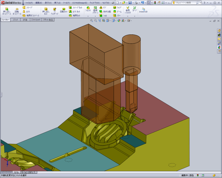
Cavity-Core Split Cavity-Core Design
A cavity-core is created by directly setting its size or specifying the amount of the clearance from the product model. You can set the dimensions while checking the size in the preview. It automatically creates the cavity part by figuring out the difference between the product model and cavity-core. The modification to the product shape will be reflected in the cavity-core shape. In order to divide the cavity-core, we provide the commands which support parting surface creation including filling holes and knitting surfaces.
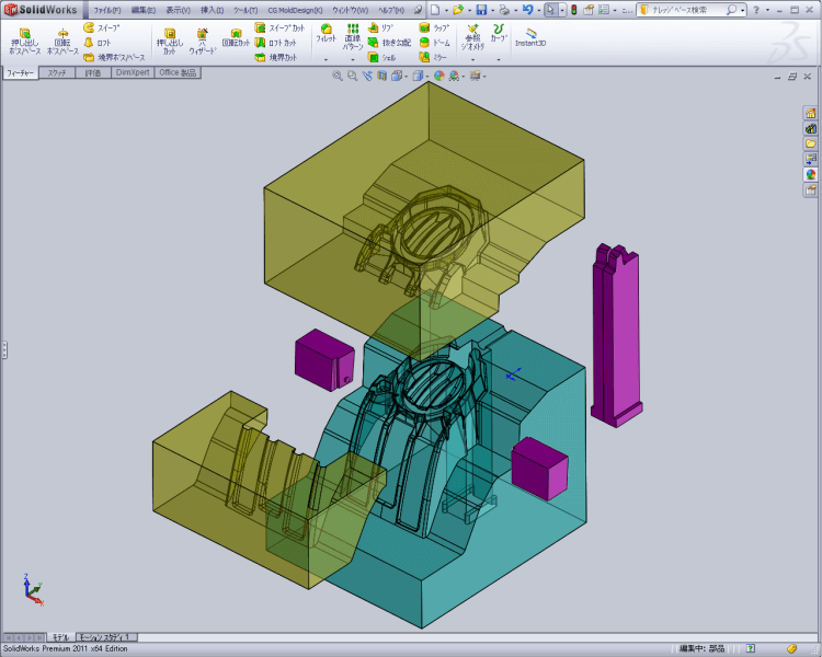
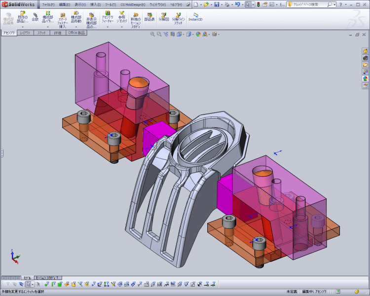
Core Pin / Insert Cavity-Core Design
Creates "Core Pin" and "Insert" from the models which are split into cavity and core,utilizing sketch or surface entities. It is possible to consider "Flange" and "Escape" for the extracted insert shape.
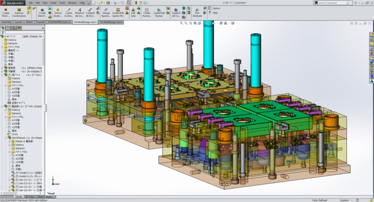
Mold Base Base / Slide Design
FUTABA standard mold base will be created automatically. Created mold base will be displayed as wire frame on mode of template base, so dimension easy to set upon checking cavity and core. And, customized mold base which is your company original is available.
Design Slide Base / Slide Design
Slide parts will be created easily, because of calculated parameter from formula. And length of angular pin will be calculated automatically through amount of undercut. And hole of angular pin will be created at the same time.
Create Ejector Pin Ejector / Mold Structure Design
It calculates heights of ejector pins based on their developed sketches and creates the standard or original pins. You can set the tip treatment, ejector lock, and machining hole attributes at the same time.
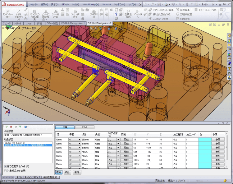
Thermoregulation Hole / Cooling Tank
Ejector / Mold Structure Design
Course of water hole will be created three-dimensional and intuitively. Positioning of cooling parts is available, and hole of pipe thread is also available. And in case of creating cooling tank, height of cooling tank will be calculated automatically with keeping thickness from sketch circle.
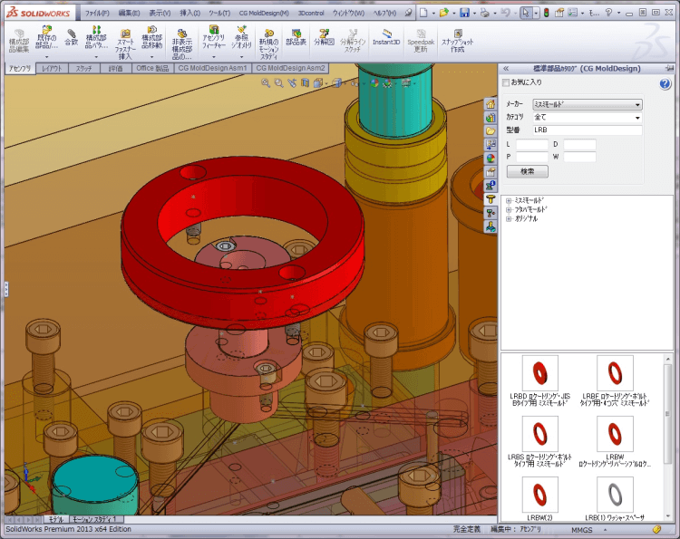
Create Standard Parts Standard Parts
CG Mold Design will support more than 4,000 standard parts of FUTABA and MISUMI. (Original parts is available to register as standard parts.) And parameter of length and position is easy to set upon checking with pre-view. Machining template is on boarded as standard, so even importunate machining attribute is available to set with one click operation. And plural parts will be registered as UNIT. Positioning and machining attribute will be kept as well.
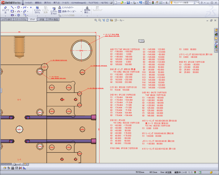
Hole Dimension / Hole List Drawing
You can create dimensions for machining holes with attributes. Also, when you specify a view, all the existing machining holes are retrieved and output to a list. The display sequence of hole attributes can be registered as a master.
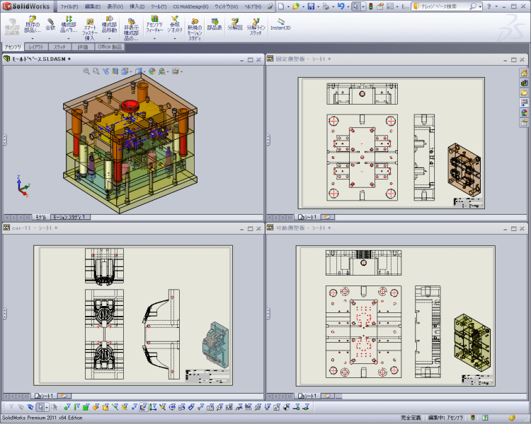
Parts Release Drawing
Whole parts from assembly will be list up on the screen, so you can select parts drawing which you want from assembly drawing. Title block, paper size, dimension and hole list will be created with parts drawing at the same time.
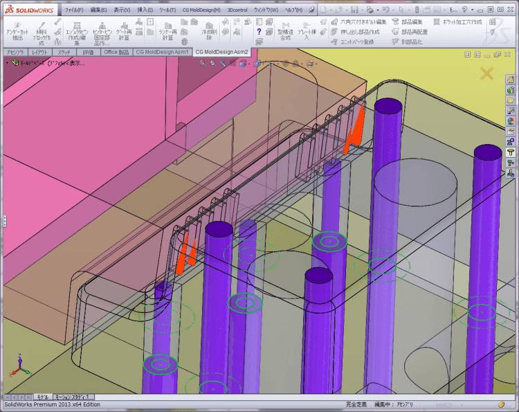
Interference confirmation of Slide and Ejector Other
You can check interference confirmation of slide core and ejector pin. System will show you place of interference between slide and ejector pin. Interference place will be colored, so easy to check the place.
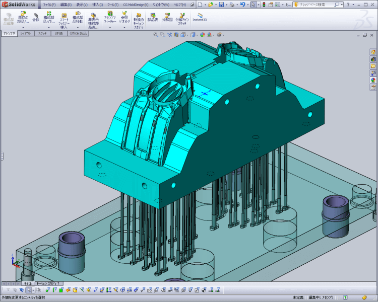
Check Simulated Molding Parts Other
It calculates the space in the specified area and makes a simulated molded part. The created shape can be saved as model data, so you can use it for flow analysis.
Electrode Other
It will create electrode from cavity and core by extracting electrode creation site. Spark Gap amount will be indicated independently, and plural electrodes also can be allocated on single base.
OTHER PRODUCT

Product Inquiry
Contact us

© Copyright 2010- C&G SYSTEMS INC. All Rights Reserved.